What to make with 30-50 hFE Germaniums

rossbalch

Active member
If anyone has followed my recent NOS [PNP] Gemanium transistor box adventures you would know I now own a large number of ~40 hFE, low leakage Germaniums. These are obviously not at all suited for Fuzz circuits, but that's ok, I like more subtle pre-amp like effects a lot of the time anyway.

My thinking was, these would be good for multi device circuits. Maybe a cascaded design? Or maybe something like a LTP into Push Pull circuit? Could the Neve preamp be adapted to use these?

Also any ideas for line level designs? Could be nice in a somewhat subtle saturation type thing.

I'm very open to hybrid designs too.

EDIT: I should mention, I'm aware of Darlington pairs, and with the low leakage, they are indeed well suited to such a purpose, but I also am not sure what kind of circuits I would want to create a Darlington pair in, given they tend to be VERY high gain, ~1600 HFE for a 2x40 HFE pair for instance.

Further edit: I'm by no means married to 9V. If a higher voltage would help then that's fine too.

Would hate to see these devices rot in a draw, I'm sure they can be utilised in various ways.
 
Last edited:
Low gain Germaniums make for really cool Fuzz Faces.

You can use a larger feedback resistor and a larger fuzz pot to get a little more gain out of it but even stock it’ll be fun.

I'm curious how low HFE affects the sound of the circuit, I've never actually built, or really even engaged with Germanium type circuits before, I fall on 2 extremes when it comes to circuits, subtle "sweetner" type effects, over drives used as boosts, and tight metal distortions.

It seems intuitive that low HFE transistors will push the next stage less hard, but what about gating and that type of stuff? Does it affect the biasing etc.
 
Let's say I made an LPB-1 but converted to PNP Germanium, and biased "optimally", would the only difference between say a 40 HFE transistor, an 80 HFE transistor be the total dB gain available, or would saturation characteristic be different too?
 
I'm curious how low HFE affects the sound of the circuit, I've never actually built, or really even engaged with Germanium type circuits before
time to get a breadboard.

im serious, if you really want to get a quick tangible grasp on what to expect from your devices, pick a circuit, breadboard it, and see how you go.
then when you find something doesn't sound (or measure) right or whatever, it's as easy pulling a resistor and plonking a different value in there and hearing the difference immediately.
people can talk numbers and theory all day, but none of it really means shit until you hear things for yourself.

Let's say I made an LPB-1 but converted to PNP Germanium
perfect candidate for your first breadboard project
 
time to get a breadboard.

im serious, if you really want to get a quick tangible grasp on what to expect from your devices, pick a circuit, breadboard it, and see how you go.
then when you find something doesn't sound (or measure) right or whatever, it's as easy pulling a resistor and plonking a different value in there and hearing the difference immediately.
people can talk numbers and theory all day, but none of it really means shit until you hear things for yourself.


perfect candidate for your first breadboard project

I actually do have a breadboard but I've never used it, but this whole endavour has deffinitely ignited my urge to learn. I've learned a lot since I first bought them so breadboarding seems a lot less intimidating now.
 
Rangemaster style circuits do well with this level of gain. It’s recommended to maybe be on the upper end of this range to a little higher but I auditioned some 30-50s in a couple of my builds and they sounded great!
 
I actually do have a breadboard but I've never used it, but this whole endavour has deffinitely ignited my urge to learn. I've learned a lot since I first bought them so breadboarding seems a lot less intimidating now.
Take a look at the Test Kitchen forum. There are tons of breadboarding tutorials with lots of hand holding. Breadboarding is intimidating until you actually do it and then wonder why you were worried in the first place.
 
I would experiment on known designs using less feedback.
When designing amplification stages, even with low gain, it is desired to use high hfe transistors with negative feedback. That compensates the big % variations of the between transistors (really good for mass production), and also makes the response more linear.
Since you are making stuff one at the time, and can use trims to adjust feedback and bias, you can use the low gain germanium transistors to get less linear response before breakup. With that, I would expect more natural cleanup on a fuzzes, and more harmonic coloration with less harshness.

Edit: It is expected that some negative feedback will be needed, since germanium changes it's propierties with temperature.
 
Last edited:
I would experiment on known designs using less feedback.
When designing amplification stages, even with low gain, it is desired to use high hfe transistors with negative feedback. That compensates the big % variations of the between transistors (really good for mass production), and also makes the response more linear.
Since you are making stuff one at the time, and can use trims to adjust feedback and bias, you can get the less linear response before breakup. With that, I would expect more natural cleanup on a fuzzes, and more harmonic coloration with less harshness.

Edit: It is expected that some negative feedback will be needed, since germanium changes it's propierties with temperature.

Regarding the feedback, these Russian Germaniums have almost undetectable leakage so I'm guessing the negative feedback will be an important parameter.
 
Check out this circuit. I breadboarded it. It wasn’t good, but I didn’t like it enough to build. I would give it a go, especially if you have a ton of low gain transistors.


I would also second the tonebender circuits. MK3 and Burns Buzzaround works well with the low gain transistors.
 
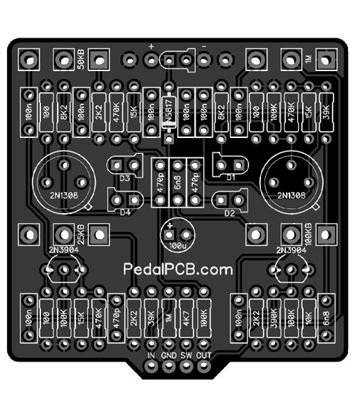
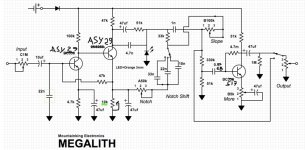
This has been my main pedal since build.

1753252968554.jpeg
Q1-2 use germ-transistors you have, 30-60hfe.
Q3 germistor or Si. I used really high gain darlington, but find no use for MORE-switch (boost) as darlington transistor used takes off fuzz’ edge too much.
 
time to get a breadboard.

im serious, if you really want to get a quick tangible grasp on what to expect from your devices, pick a circuit, breadboard it, and see how you go.
then when you find something doesn't sound (or measure) right or whatever, it's as easy pulling a resistor and plonking a different value in there and hearing the difference immediately.
people can talk numbers and theory all day, but none of it really means shit until you hear things for yourself.


perfect candidate for your first breadboard project

Ok, so I have decided to try my hand at the PNP Ge LPB-1 breadboarding. And wouldn't you know it, there's already a guide to do that (sort of)

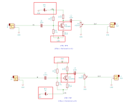
I wanted to ask a clarifying question though, in this example below, this to me looks a lot like the "turning the circuit upside down" mentioned in the Small Bear article on the Rangemaster.

Specifically:
I have a PNP device, and I really want to build and run negative ground. Can I "turn the circuit upside down" to do that?

A: It has been done, it sometimes works and sometimes oscillates badly. Not recommended.

However Barbarach has this to say:
This is important because lots of times it is said that circuit can be adapted from NPN to PNP transistor by simply reversing battery polarity. In reality, it is slightly more complicated than this.

You only swap polarity for the amplifier – and that’s what I highlighted above. If you’d swap the polarity completely, jacks would be connected to 9V instead to GND and that might not be the healthiest option for subsequent pedals/amp.

I feel like I'm missing some understanding here, whether it be what "swap the polarity completely" actually means or otherwise. Why would simply swapping the battery polarity affect the jacks?

1753315285451.png
 
Back
Top