Feral Feline
Well-known member
TLDR? See "UPSHOT" at bottom.
My Q-Tune arrived a week ago, Wednesday, after a minor hiccup with shipping (which Q-Tune’s Dynamic Duo sorted out for me, thank you again gents).
Then the universe conspired against me building it. Emergency car-rescue for a friend; grocery-shopping, banking with/for my wife, friend’s wife’s birthday-barbeque, family-drama, daily-driver in the fixit-shop, etc… So I chipped away at it whenever I could carve out a solid block of time.
I had meant to build a couple of small pedals prior to tackling the Q-Tune as it’s been a while, however I didn’t get the chance to freshen up my soldering-skills beforehand.
Well packed and organised, as Audandash noted in his first impressions thread. What struck me in particular was that the PCB seemed to be of a very high quality.
I started out with 375ºC and a Small chisel-tip — 37/63 solder .5-gauge but I wasn’t happy with how the first diode went in so I changed to the .6-gauge solder (37/63). While I’ve got some .8, I was worried I’d flood things, it’s been a while since I soldered.
Turned out I could’ve used my thickest gauge, I was having to feed a lot of .5 solder on the resistors. To begin I wasn’t letting the iron heat things up enough before applying solder, but I eventually found my rhythm by the end of the resistors and moved on to the MLCC caps.
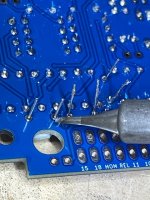
From there things went downhill, well, okay faster downhill. The PCB’s MLCC-pads weren’t heating up for me and the solder wasn’t flowing and I was getting mighty frustrated — was it the tiny pads or was it me? Nobody else has commented about problematic pads. I quit after just two (2) MLCCs.
 MLCC MADNESS!
The next day I tried different tips, different gauges of solder and different techniques/angles/adjustments… and it was all still hit and miss, mostly miss. C19 specifically did not want to be soldered, extremely reticent, but nearly every MLCC fought me tooth and nail, even after upping the temp to 395º.
I checked all the components as I went, which really slowed me down but I wanted (née needed) this thing to work from the git-go; been a while since I had a win, which is why it’s been a while since I built anything.
Most of what I checked was very close to spec, but a couple of caps came close to colouring outside the spec lines, a 470n that measured 450n for example and a 10µ that went beyond 20%, measuring about 7µ5.
The JST-12pin’s wires were too small for my wire-stripper so I hand rolled them over a utility-knife blade. The middle red wire shed a bunch of strands and I prayed it wasn’t one of the important ones (it wasn’t).
There were a few days where I couldn’t work on it, such as the day it arrived, the weekend, yesterday... So today I was determined to finish it.
Out of frustration I swapped to the original conical tip that came with the Hakko, haven't used it in ages, and things went much better. I was nearing the end of soldering, I had two caps left, the last 47µ and a 220µ. I installed the 47µ first, and for once had good solder-flow, it was the first thing to be in nice and neat, super tight, a perfect install. Well…
Throughout I was checking back and forth between my build and the doc, yet I still INSTALLED THE 47µ IN THE 220µ’s SPOT. GRRRRR . I think that’s the first time I’ve done that kind of mistake. I considered soldering the 220µ to the underside and grab another 47µ, but I think I’m out of 47µ.
The solder-sucker got rid of the bulk of solder, then I resorted to braid (been years since I used braid) with flux-paste — yet it wasn’t coming out…

Took a long break to let myself and the iron’s tip cool down.
First time seeing Popeye meeting Sindbad the Sailor…
Needed more cool...The Pink Panther cracking a safe…
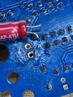
After cooling off I went calmly back to work, and back to my broad chisel-tip to help heat up the pads and 47µ’s legs. Snipped its leads close to the board and proceeded to coax the cap out with heat, each side a bit at a time.
 OUT! OUT DAMNED SPOT!
TESTAMENT TO THE BOARD’s QUALITY — I DIDN'T PULL UP A TRACE OR PAD!
Once out, I tried the solder-sucker again to get the negative-pad a bit cleaner, and it worked thankfully making my 0.79mm drill-bit redundant. HAND-Drilling solder out of PCB pads is laborious and time-consuming, but if you go power or fast, you break the bit, the pad or both.
The long screws for the N1 enclosure — wasn’t clear where they should be placed, but I figured it out after re-RTFM. I gave the stand-off screws 2mm above the lip of the enclosure, following Hammond enclosure spec, even though this is a Tayda enclosure.
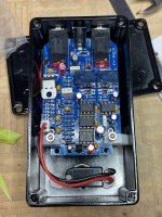
After about 10 hours total, spread over a week, I finished building & testing it.

Hallelujah brothers and sisters, it works — no cold solder joints (that I know of) on the MLCCs, no fried traces/components, wires intact…
~~~~~~~~~~~~~~~~~~~~~~~~~~~~~~~~~~~~~~~~~~~~~~~~~~~~~~~~~~~~~~~~~~~~~~~~~~~
If I get another one, I’ll save the JST-12pin for next-to-last soldering, after everything else but just before installing the TO-220 Regulator. That way it’s not in the way, no chance of burning a wire or breaking one off while soldering the electrolytics etc.
ALSO, I’ll solder the momentary switch’s wires up while the iron’s hot. According to the build doc, it’s to be soldered after fixing up the PCB’s hardware Board-Mounts, but there’s no need to separate it from the other soldering, it’s got a JST quick-connect.
I thought about putting this missive in the Q-Tune subforum, but it’s a build-report so here ’tis.
UPSHOT:
It’s a great-looking unit with thick glossy paint, and everything is of a high-quality, and it’s been well thought out.
I can’t wait to dig in to the functions to tailor it further to my needs.
My Q-Tune arrived a week ago, Wednesday, after a minor hiccup with shipping (which Q-Tune’s Dynamic Duo sorted out for me, thank you again gents).
Then the universe conspired against me building it. Emergency car-rescue for a friend; grocery-shopping, banking with/for my wife, friend’s wife’s birthday-barbeque, family-drama, daily-driver in the fixit-shop, etc… So I chipped away at it whenever I could carve out a solid block of time.
I had meant to build a couple of small pedals prior to tackling the Q-Tune as it’s been a while, however I didn’t get the chance to freshen up my soldering-skills beforehand.
Well packed and organised, as Audandash noted in his first impressions thread. What struck me in particular was that the PCB seemed to be of a very high quality.
I started out with 375ºC and a Small chisel-tip — 37/63 solder .5-gauge but I wasn’t happy with how the first diode went in so I changed to the .6-gauge solder (37/63). While I’ve got some .8, I was worried I’d flood things, it’s been a while since I soldered.
Turned out I could’ve used my thickest gauge, I was having to feed a lot of .5 solder on the resistors. To begin I wasn’t letting the iron heat things up enough before applying solder, but I eventually found my rhythm by the end of the resistors and moved on to the MLCC caps.
From there things went downhill, well, okay faster downhill. The PCB’s MLCC-pads weren’t heating up for me and the solder wasn’t flowing and I was getting mighty frustrated — was it the tiny pads or was it me? Nobody else has commented about problematic pads.
 MLCC MADNESS!
The next day I tried different tips, different gauges of solder and different techniques/angles/adjustments… and it was all still hit and miss, mostly miss. C19 specifically did not want to be soldered, extremely reticent, but nearly every MLCC fought me tooth and nail, even after upping the temp to 395º.
I checked all the components as I went, which really slowed me down but I wanted (née needed) this thing to work from the git-go; been a while since I had a win, which is why it’s been a while since I built anything.
Most of what I checked was very close to spec, but a couple of caps came close to colouring outside the spec lines, a 470n that measured 450n for example and a 10µ that went beyond 20%, measuring about 7µ5.
The JST-12pin’s wires were too small for my wire-stripper so I hand rolled them over a utility-knife blade. The middle red wire shed a bunch of strands and I prayed it wasn’t one of the important ones (it wasn’t).
There were a few days where I couldn’t work on it, such as the day it arrived, the weekend, yesterday... So today I was determined to finish it.
Out of frustration I swapped to the original conical tip that came with the Hakko, haven't used it in ages, and things went much better. I was nearing the end of soldering, I had two caps left, the last 47µ and a 220µ. I installed the 47µ first, and for once had good solder-flow, it was the first thing to be in nice and neat, super tight, a perfect install. Well…
Throughout I was checking back and forth between my build and the doc, yet I still INSTALLED THE 47µ IN THE 220µ’s SPOT. GRRRRR
The solder-sucker got rid of the bulk of solder, then I resorted to braid (been years since I used braid) with flux-paste — yet it wasn’t coming out…
Took a long break to let myself and the iron’s tip cool down.
First time seeing Popeye meeting Sindbad the Sailor…
Needed more cool...The Pink Panther cracking a safe…
After cooling off I went calmly back to work, and back to my broad chisel-tip to help heat up the pads and 47µ’s legs. Snipped its leads close to the board and proceeded to coax the cap out with heat, each side a bit at a time.
 OUT! OUT DAMNED SPOT!
TESTAMENT TO THE BOARD’s QUALITY — I DIDN'T PULL UP A TRACE OR PAD!
Once out, I tried the solder-sucker again to get the negative-pad a bit cleaner, and it worked thankfully making my 0.79mm drill-bit redundant. HAND-Drilling solder out of PCB pads is laborious and time-consuming, but if you go power or fast, you break the bit, the pad or both.
The long screws for the N1 enclosure — wasn’t clear where they should be placed, but I figured it out after re-RTFM. I gave the stand-off screws 2mm above the lip of the enclosure, following Hammond enclosure spec, even though this is a Tayda enclosure.
After about 10 hours total, spread over a week, I finished building & testing it.

Hallelujah brothers and sisters, it works — no cold solder joints (that I know of) on the MLCCs, no fried traces/components, wires intact…
~~~~~~~~~~~~~~~~~~~~~~~~~~~~~~~~~~~~~~~~~~~~~~~~~~~~~~~~~~~~~~~~~~~~~~~~~~~
If I get another one, I’ll save the JST-12pin for next-to-last soldering, after everything else but just before installing the TO-220 Regulator. That way it’s not in the way, no chance of burning a wire or breaking one off while soldering the electrolytics etc.
ALSO, I’ll solder the momentary switch’s wires up while the iron’s hot. According to the build doc, it’s to be soldered after fixing up the PCB’s hardware Board-Mounts, but there’s no need to separate it from the other soldering, it’s got a JST quick-connect.
I thought about putting this missive in the Q-Tune subforum, but it’s a build-report so here ’tis.
UPSHOT:
It’s a great-looking unit with thick glossy paint, and everything is of a high-quality, and it’s been well thought out.
I can’t wait to dig in to the functions to tailor it further to my needs.

