You are using an out of date browser. It may not display this or other websites correctly.
You should upgrade or use an alternative browser.
You should upgrade or use an alternative browser.
Nobelium - tube bass preamp project
- Thread starter vigilante398
- Start date
Tassieviking
Active member
What is the actual voltage that is going into the pedal ?
Cheap power supplies can often provide a lot higher voltage then they claim, the ALD7555 timer IC you used should only be used between 2V to 10V so you should never run the pedal at more then 10V.
I would replace the ALD7555 with a 555 timer just in case someone plugs a 12V supply into that pedal in the future.
I would guess that the problem might be the power supply causing the noise but it is a guess at this stage.

Hey guys,
finished my Nobelium.
I can confirm, that the Neutrik NC3MAV fits perfectly and is a really good alternative for the Amphenol XLR.
The build went really well and fired up straight after plugin the 9vdc.
I used Matt black powder coating enclosure from Tayda, but I really had to stripe the powdercoating off. After using the faceplate the next bummer. The potentiometer don’t take the nut. So I had to take the file and remove some aluminium from the inside of the enclosure. Then everything worked.
Don’t know why this happened, cause I see that also other builders used the faceplate with a powder coated enclosure.
The sound is awesome !
The build is relatively easy for experienced builders.
Thanks @vigilante398 for this kit !


Nice work TillMack!! Looks great ")
I've had the same trouble, often the pots have a small tab which need to be taken off. I just do it automatically now as I don't like how the tabs tend to skew the pot's alignment. Also, when using a powder coating and face-plate, I would sand flat the pot nut on one side so it grabs the thread. Usually together it's enough.

I've had the same trouble, often the pots have a small tab which need to be taken off. I just do it automatically now as I don't like how the tabs tend to skew the pot's alignment. Also, when using a powder coating and face-plate, I would sand flat the pot nut on one side so it grabs the thread. Usually together it's enough.


Tassieviking
Active member
When I do the pots and switches I always place them on the PCB and then I carefully line it up with the box and then screw the pots and switches down hard before I solder the pots and switches.
You need to have the pots and switches mounted in the box before you solder them in, sometimes I put a small dab of solder on the middle pot leg to hold it in place while I mount it in the box and tighten them down. ( re-solder the middle leg first to take any strain out if you solder it first)
Usually it is enough to spread the legs a little bit so the pots hold themself in place though.
We do not want any strain on the solder joints when we assemble the box and that can easily happen if we solder the pots and switches in place on the PCB without mounting them in the box first.
If you are having a bad day already it can be a pain in the behind to align everything while trying to keep the pots sitting on the PCB when you try to mount the whole lot in the box though, I might have said bum and pubic hair and similar bad words when nothing wants to work.
I see you placed a connector on the DC power so it is easier to remove the PCB later on, I like that idea.
I have been using a Cliff DC 2.1mm external thread jack for a long time because I like being able to remove the PCB without de-soldering the power jack, I haven't used them on any C2CE projects yet but I might start doing it again.
Tayda has a clone of the Cliff jack but I get the Cliff ones from https://www.diyguitarpedals.com.au/shop/index.php?main_page=product_info&cPath=37&products_id=617
Love My Switches also has them as well as many others, https://lovemyswitches.com/cliff-sw...U359WqZ0yLWfLtTpgR7vyMztP6DMx2avWunmKdww7otAJ
When I do the pots and switches I always place them on the PCB and then I carefully line it up with the box and then screw the pots and switches down hard before I solder the pots and switches.
You need to have the pots and switches mounted in the box before you solder them in, sometimes I put a small dab of solder on the middle pot leg to hold it in place while I mount it in the box and tighten them down. ( re-solder the middle leg first to take any strain out if you solder it first)
Usually it is enough to spread the legs a little bit so the pots hold themself in place though.
We do not want any strain on the solder joints when we assemble the box and that can easily happen if we solder the pots and switches in place on the PCB without mounting them in the box first.
If you are having a bad day already it can be a pain in the behind to align everything while trying to keep the pots sitting on the PCB when you try to mount the whole lot in the box though, I might have said bum and pubic hair and similar bad words when nothing wants to work.
I see you placed a connector on the DC power so it is easier to remove the PCB later on, I like that idea.
I have been using a Cliff DC 2.1mm external thread jack for a long time because I like being able to remove the PCB without de-soldering the power jack, I haven't used them on any C2CE projects yet but I might start doing it again.
Tayda has a clone of the Cliff jack but I get the Cliff ones from https://www.diyguitarpedals.com.au/shop/index.php?main_page=product_info&cPath=37&products_id=617
Love My Switches also has them as well as many others, https://lovemyswitches.com/cliff-sw...U359WqZ0yLWfLtTpgR7vyMztP6DMx2avWunmKdww7otAJ
Thanks for your advice, but I already done that.
The powdercoating was too thick, even when I try to install the pots without the pcb, I can’t put the nut on them. I think with a non powercoated enclosure it will be easier.
But as you can see, it now works.
I use the dc connector on all of my builds, cause I hate desoldering, when I have to repair something and need the pcb.
Last edited:
SebastiánBass
New member
Hey guys... I already have my Noblelium 
 all wired and tested, it worked perfect the first time! I modified some things to make some aesthetic changes position to the cabinet, then I will publish photos...
My question is where could I place an EQ bypass in the schematic? I could go directly with a true bypass but I think the XLR would not work... ok my friends, I hope you can help me!
Thank you very much
Sorry if my English isn't good! I'm from Argentina.
all wired and tested, it worked perfect the first time! I modified some things to make some aesthetic changes position to the cabinet, then I will publish photos...My question is where could I place an EQ bypass in the schematic?
I could go directly with a true bypass but I think the XLR would not work... ok my friends, I hope you can help me!Thank you very much
Sorry if my English isn't good! I'm from Argentina.
Isn’t that just a standard fender style tone stack between the first valve stage and the HPF?My question is where could I place an EQ bypass in the schematic?
Tassieviking
Active member
I just noticed that it looks like the 1/4" output seems wired in reverse, the signal is wired to the shield ring and the ground is wired to the tip on the socket.Forget the inside shot.
Here it is.
Nothing special. Used some RFT ECC82 tubes I found in an electrical store here in Germany.
View attachment 96801
If the 1/4" out works the socket must be insulated from the box by the powder coating only, it would be best if the wires were reversed to the correct position.
I must have looked at the picture lots of times and not noticed until now.
Cheers
Mick
SebastiánBass
New member
Hi! Thanks for the comment. I understand what you're referring to, but I think it's not a bad idea to have the option. Note that C2C thought the same and added it to their latest assembled version or pedal for sale..Isn’t that just a standard fender style tone stack between the first valve stage and the HPF?
 . Thanks!
Attachments
Tassieviking
Active member
The most common way to bypass a fender tone stack is to lift the ground leg on the MID pot, the Nobelium has a resistor instead of a MID pot so just disconnect R21 2k7 ohm resistor and that should work.Hey guys... I already have my Noblelium
My question is where could I place an EQ bypass in the schematic?
Thank you very much
Sorry if my English isn't good! I'm from Argentina.
You could also replace R21 with a pot to make a MID pot if you want to experiment more with the circuit, but keep a switch on the ground leg of the MID pot if you want to disconnect the tone stack still.
Tassieviking
Active member
I think what the new switches on that Nobelium that is for sale do is connect the 1/4" input directly to the 1/4" output, also the XLR transformer is connected directly to the 1/4" input socket.Hi! Thanks for the comment. I understand what you're referring to, but I think it's not a bad idea to have the option. Note that C2C thought the same and added it to their latest assembled version or pedal for sale..
It is a way of bypassing all the electronics in the pedal itself, if you loose power to the pedal you can still get signal to both outputs, the 1/4" signal just goes in and out but the XLR still works through the transformer.
For a passive DI all you need is one of the XLR transformers and a 1/4" socket for input and an XLR socket for output and a box to mount it all in.
I could of course be wrong but that is what I think and that is something I might try on my next Nobelium.
Pedalnetics does just that with their tiny DI box but with a few passive components for ground lift and damping of the signal.
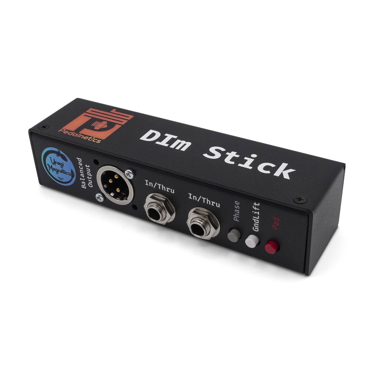
DIm Stick - Pedalnetics
DIm(ono) Stick is rocking a transformer from Unagi Magnetics, which is the house-brand from our friends over at SushiBoxFX! This is the same transformer they use in the tube-based Finally DI and the Venus Z. The frequency response is the flattest we've seen out of multiple transformers, which...
 pedalnetics.com
Last edited:
vigilante398
Authorized Vendor
Hi! Thanks for the comment. I understand what you're referring to, but I think it's not a bad idea to have the option. Note that C2C thought the same and added it to their latest assembled version or pedal for sale..
Tassie nailed it, those switches bypass the entire circuit, not just the tonestack.I think what the new switches on that Nobelium that is for sale do is connect the 1/4" input directly to the 1/4" output, also the XLR transformer is connected directly to the 1/4" input socket.
It is a way of bypassing all the electronics in the pedal itself, if you loose power to the pedal you can still get signal to both outputs, the 1/4" signal just goes in and out but the XLR still works through the transformer.
If you want to do a quick and dirty bypass of the tonestack, lift the ground on the bottom leg of R21. Otherwise you'll be looking at adding a new coupling capacitor (I would use 100nF, make sure you use high voltage) to go from the tube's anode to the middle lug of the Treble pot.