Help measuring SMD JFETS

comradehoser

Well-known member
I am trying to follow Chucks wisdom rebuilding the Deofol with properly sequenced J201s. But I've run out of through-hole, so now I have 20 little grains of effing rice to try to measure to find target IDSS and VP.

I thought it would be as easy as making a viable test bed and plugging it in to the venerable TC1, but nooooooo. Of course not.

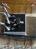
The idea is simple for the test bed and seems to be working as designed--I took a block of scrap wood, cut out a little snug well for the smd, laid down some copper shielding tape with the corners in the well, and mounted the smd upside down so that the legs contact the tape that is overlapping the edge of the well. a piece of foam and a rubber band ensures proper contact and maintenance.

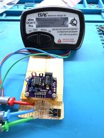
I have positive contact between the three legs of the smd and the soldered component legs. But the TC1 keeps returning a diode or nonfunctional component reading.

Putting a TO-72 package regular size JFET on the copper tape yields a proper reading (how valid and accurate is not really important at this point), so it seems like the TC-1 in particular has a difficult time reading JFET SMDs. Any idea on how to remedy this or any workarounds?

IMG_20251004_221326136.jpg
.
 
Last edited:
Came across owlexifry and Chuck's convo https://forum.pedalpcb.com/threads/jfet-shootout.13363/reply?quote=178707

Made the "little tester" on breadboard with MMBFJ201 and a 1m resistor, 9v power supply. Getting kind of variable readings depending on angle and pressure on the JFET in the jig, and my SMDs report ranged from .053 IDSS and .536 VP to 0.133/.872 so maybe it's not so exact (?). Hopefully it's good enough to ballpark Deofol JFETS up in there.
 
i put copper tape on a sheet of acrylic and push down the transistor (not upside down) with a rubber block and it measures successfully on 9 out of 10 tries or so
 
One thing I learned just today, SMD jfets are magnetic.
If you do as @pettert suggests and built a jig on some acrylic sheeting you can hold the jfet in place with a magnet under it.

*Note, I have not verified this so YMMV. But someone on this forum has designed some PCB's of a Keen SMD tester and we're going to try the magnet trick and see if it works.
 
WEll that is a very handy trick! For soldering for sure, and also for sticking on an SMD board with leads to test. I wonder if it would screw with the readings, though.

My issue is that the TC1 can apparently read through-hole JFETS but not SMD. I don't know why. I guess I will just gut it out with the "small board" owlexifry method breadboarded. Might be more accurate, in any event.


Yup, the magnet trick works. Check this out......
 
I never tried it with my TC7 (TC1 in disguise). I've been using my Peak Atlas.

So here's a couple of choices that will make it work easier.

RullyWow's free Jfet matcher board. If I still had any I'd send you one. But it's only $7 for 3 at OshPark.

And my Nashville buddy @Audandash just whipped up this new matcher board, based on the same RG Keen schema.

unnamed.jpg

Still working out the magnet thing. I believe he said he tried measuring a 2N5457 this morning then launched across the room.
Those damn things have a life of their own I swear! I'm thinking of maybe an adhesive magnet. I've seen them on Amazon. The little round disk.
 
Yeah, I tested out the idea. The SMDs are super magnetic and will leap towards the magnet, it's true. Buuut, I tried several different types and orientations of magnets, and in each case, the SMD wanted to stand on end, unfortunately. I don't have the similar style bar magnet as you have (is it a pickup alnico?).
 
@comradehoser

Check this out.

I cut a small piece of an A2 bar magnet then stuck an SMD adapter on with some double sided tape.

Yes, the jfets are fiddly about the magnetic field but I can find the sweet spot on the magnet by putting the jfet on the adapter then sliding the adapter around on the magnet unit the legs line up correctly. Then tape the adapter on the magnet with the double sided tape.
Now the SMD JFets "jump" onto the pads correctly. Check out the video below.

I used my Peak for this pic but you can see I can easily hook it up to my Keen matcher board as well.

IMG_8238 2.JPG

IMG_8239.JPG


Attachments

  • IMG_8238.JPG
    IMG_8238.JPG
    419.5 KB · Views: 1
  • IMG_8239.JPG
    IMG_8239.JPG
    286.7 KB · Views: 1
  • IMG_8238.JPG
    IMG_8238.JPG
    419.5 KB · Views: 1
The DCA75 is great, it's just not very rugged...

I've already had to repair the leads once. The buttons don't always spring back like they should anymore. The MicroUSB port is surely due to start acting flaky any day.

It just wasn't designed for the kind of abuse it gets around my bench... so I thought I might try to rehouse it in a 125B or similar, with some durable switches and a USB-B (or maybe even toss a USB-C converter in there) ..

I cracked it open to see how difficult it might be, and was really surprised at what I saw inside. I don't know exactly what I was expecting, but I don't think I was expecting to see a plain old PIC microcontroller, a DC/DC step-up converter, and a bunch of analog switches.....

That got me thinking...

If we already know how to test these components manually with a DMM and voltmeter, and we can read analog voltages with our microcontroller, and we can produce voltages with a step-up converter and our microcontroller..... why couldn't we just build our own?

Then you come along with this magnet trick, and I'm imagining a little neodymium magnet positioned beneath a faceplate with SMD pads on top...
 
The DCA75 is great, it's just not very rugged...

I've already had to repair the leads once. The buttons don't always spring back like they should anymore. The MicroUSB port is surely due to start acting flaky any day.

It just wasn't designed for the kind of abuse it gets around my bench... so I thought I might try to rehouse it in a 125B or similar, with some durable switches and a USB-B (or maybe even toss a USB-C converter in there) ..

That got me thinking... why couldn't we just build our own?
It is definitely not made for the industrial use it gets around here, had to repair the leads several times, and buttons are super fidldy with time..
I vouch for the project wishlist of a DCA75 PCB :love: :love:
 
The DCA75 is great, it's just not very rugged...

I've already had to repair the leads once. The buttons don't always spring back like they should anymore. The MicroUSB port is surely due to start acting flaky any day.

It just wasn't designed for the kind of abuse it gets around my bench... so I thought I might try to rehouse it in a 125B or similar, with some durable switches and a USB-B (or maybe even toss a USB-C converter in there) ..

I cracked it open to see how difficult it might be, and was really surprised at what I saw inside. I don't know exactly what I was expecting, but I don't think I was expecting to see a plain old PIC microcontroller, a DC/DC step-up converter, and a bunch of analog switches.....

That got me thinking...

If we already know how to test these components manually with a DMM and voltmeter, and we can read analog voltages with our microcontroller, and we can produce voltages with a step-up converter and our microcontroller..... why couldn't we just build our own?

Then you come along with this magnet trick, and I'm imagining a little neodymium magnet positioned beneath a faceplate with SMD pads on top...
Yah, I worry about the leads on mine. It looks to be made with the same quality as the cheapo Amazon jumper wires. Hmmmm.....a 1590b with some jacks for test leads. Or spring loaded speaker connectors type. And a magnetized pad on top.

Check out the little testing pad in the lower left.
1759847105365.png
 
Yeah I was thinking high quality banana connectors or even DMM style jacks... it doesn't much matter what type, as long as there are some decent leads available with that type of connector.

I'm not suggesting we can "clone" the DCA75, we couldn't touch their code even if we could dump it from the IC... but we really shouldn't need to.

I think it's reasonable to say we could come up with something that does what we need, and that we can modify or extend to do more.

My DCA75 doesn't measure lower voltage zener diodes accurately. (I bought the ZEN50 thinking it would... it doesn't either)

It doesn't measure 2N6027's without tacking on a resistor (thanks to @PapaBear for that little bit of info)....

And wouldn't it be cool if we could measure/plot curves on LDRs and vactrols?

Or had some sort of component "matching" mode where we specify criteria or provide a baseline component and then quickly swap components blindly while listening for an audible indicator that some particular parameter was within our specified range?
 
I've been thinking about getting a DCA75 finally, and this fragility has been on my mind since I saw Robert post a pic of (I guess second time) needing to have the leads repair, and I think we're definitely on the right track with enclosing it somehow so that the DCA75 and its parts and ports don't move at all...

1759850488544.png

This drawing is rough, but something like a 3D printed enclosure with a front bezel to completely encapsulate it. Connect internally once, external connect everything else. Have some case guts that sire up to one of those ZIF multi-pin deals, maybe even have an adapter so a USB micro cable plugs in, connects to a USB-A female or even USB-C connector so that is the socket that gets the abuse.

Top bezel has cutouts for display (maybe some strip LEDs to illuminate the stone-age LCD...), buttons, and the eventual ZIF connector.

Again, very rough since I don't even have one and can't manipulate it to make some kind of case for it. The design could also accommodate an SMD footprint PCB (even magnetic; something as simple as a rare earth magnet under the test pads PCB).
 
I mostly have rare earth magnets and the fields were making the smd stand on end (the two prong side). It could be a case of too much of a good thing or maybe I need to position it better as suggested by MichaelW. Will test again.
 
Back
Top