comradehoser
Well-known member
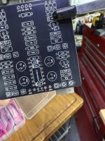
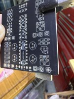
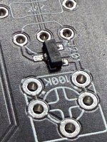
I am trying to follow Chucks wisdom rebuilding the Deofol with properly sequenced J201s. But I've run out of through-hole, so now I have 20 little grains of effing rice to try to measure to find target IDSS and VP.
I thought it would be as easy as making a viable test bed and plugging it in to the venerable TC1, but nooooooo. Of course not.
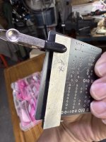
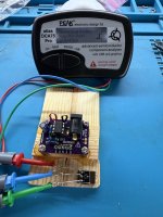
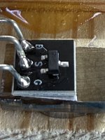
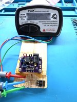
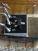
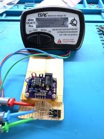
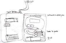
The idea is simple for the test bed and seems to be working as designed--I took a block of scrap wood, cut out a little snug well for the smd, laid down some copper shielding tape with the corners in the well, and mounted the smd upside down so that the legs contact the tape that is overlapping the edge of the well. a piece of foam and a rubber band ensures proper contact and maintenance.
I have positive contact between the three legs of the smd and the soldered component legs. But the TC1 keeps returning a diode or nonfunctional component reading.
Putting a TO-72 package regular size JFET on the copper tape yields a proper reading (how valid and accurate is not really important at this point), so it seems like the TC-1 in particular has a difficult time reading JFET SMDs. Any idea on how to remedy this or any workarounds?

.
I thought it would be as easy as making a viable test bed and plugging it in to the venerable TC1, but nooooooo. Of course not.
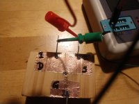
The idea is simple for the test bed and seems to be working as designed--I took a block of scrap wood, cut out a little snug well for the smd, laid down some copper shielding tape with the corners in the well, and mounted the smd upside down so that the legs contact the tape that is overlapping the edge of the well. a piece of foam and a rubber band ensures proper contact and maintenance.
I have positive contact between the three legs of the smd and the soldered component legs. But the TC1 keeps returning a diode or nonfunctional component reading.
Putting a TO-72 package regular size JFET on the copper tape yields a proper reading (how valid and accurate is not really important at this point), so it seems like the TC-1 in particular has a difficult time reading JFET SMDs. Any idea on how to remedy this or any workarounds?
.
Last edited:

