Episode booster (from musikding)

leurne

New member
hello all
i've made a episode booster, thinking it is easy enough for me....
but... It doesn't work :'( i get a bad and big buzz even when the pedal is not activated. When i activated i get no sound...

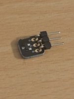
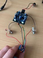
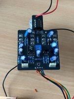
i've attached the picture. I had some question about the transistor... I install a 2N5457 instead of a very small supply by musikding. And the other one doesn't have the same name than on the drawing.

when i turn on the pedal it's turning ON, and i get the led light.

Seems the solderings are fine....
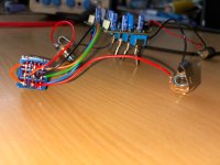
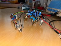
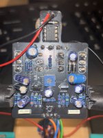
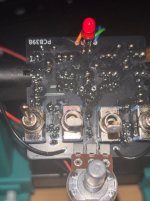
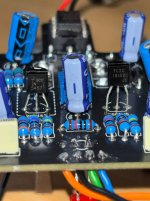
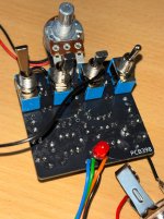
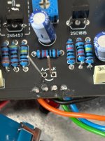
 

Attachments

  • IMG_9172.jpeg
    IMG_9172.jpeg
    306.9 KB · Views: 17
  • IMG_9173.jpeg
    IMG_9173.jpeg
    360.1 KB · Views: 16
  • IMG_9174.jpeg
    IMG_9174.jpeg
    354 KB · Views: 16
  • IMG_9175.jpeg
    IMG_9175.jpeg
    389.5 KB · Views: 14
  • IMG_9171.jpeg
    IMG_9171.jpeg
    288.6 KB · Views: 15
i get a bad and big buzz even when the pedal is not activated.
When the pedal is not activated, the only things in the circuit are the footswitch and the input and output jacks.

I’d start there and solve that problem before going any further.

Your wiring connections look right to me, but it sounds like something isn’t right,
 
When the pedal is not activated, the only things in the circuit are the footswitch and the input and output jacks.

I’d start there and solve that problem before going any further.

Your wiring connections look right to me, but it sounds like something isn’t right,
I agree! Before I was using the small pdb but I over heated it (because installed it in the wrong side 😅)
So I’ve preferred to use another foot switch with the simple wiring…

But i didn’t change anything.
If the foot switch is right, could it be the jack plug?
 

Attachments

  • IMG_9179.jpeg
    IMG_9179.jpeg
    627.6 KB · Views: 12
  • IMG_9180.jpeg
    IMG_9180.jpeg
    644.3 KB · Views: 12
Yeah! I’m glad you added those pics. Looks to me like your jacks are backwards.

If you look close you can see where the terminals connect to. Guitar signal is on the tip, so your signal wire to the footswitch should connect to the long part of the jack that touches the cable tip.
 
Yeah! I’m glad you added those pics. Looks to me like your jacks are backwards.

If you look close you can see where the terminals connect to. Guitar signal is on the tip, so your signal wire to the footswitch should connect to the long part of the jack that touches the cable tip.
Ok I don’t know how but I’ve reply to another post about the episode booster 😓

I’ve made the modifications and now it’s working perfectly ❤️❤️ but when I turn it on, the led is lighting but no sound (even from the guitare)
 
i've redone all the welding, i was afraid of a cold one. but still nothing when i plug my guitar. I'm wondering if the transistor that musikding gave me should be install instead of the 2N5457?
 

Attachments

  • IMG_9209.jpeg
    IMG_9209.jpeg
    502.6 KB · Views: 10
  • IMG_9208.jpeg
    IMG_9208.jpeg
    493.6 KB · Views: 10
  • IMG_9207.jpeg
    IMG_9207.jpeg
    187 KB · Views: 10
i've tried with another one for pedal board, and same result, 9volt DC nothing, and 18 volt DC nothing.
9v is what you want. I can tell you if you plugged an 18v your charge pump is toast. That’s what I was going after. They are very sensitive to over voltage. Anything over 10v and they are usually fried. I was just trying to rule out the simple stuff. In most cases that’s what it is, something simple. Do you have another charge pump you can try?
 
9v is what you want. I can tell you if you plugged an 18v your charge pump is toast. That’s what I was going after. They are very sensitive to over voltage. Anything over 10v and they are usually fried. I was just trying to rule out the simple stuff. In most cases that’s what it is, something simple. Do you have another charge pump you can try?
i can replace the capacitor with others (but the capacitor was given for 25v)
if i measure the voltage over the capacitor i should be able to see if it's fried?
 
It’s not the capacitor I am worried about. It’s the charge pump itself. I see this one has a switch for 9v and 18v. I thought you plugged in 18v (that’s my bad). Use your Dmm to verify on pin 8 of your ic that it has 9v and 18v depending on the switch. Pin 8 is the top right. Let’s start there and make sure power is good. Then we can move on.
 
Back
Top