Reverb Tank Issue

Vild

Active member
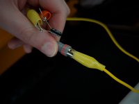
If anyone happens to know much about reverb tanks I could use some help. I have an Ampeg vh140c with what seems to be the appropriate spec reverb tank. 4bb3c1b

I've tried it both ways and smacked the tank and both sides sent audio which should mean both half of the tanks are working correctly.
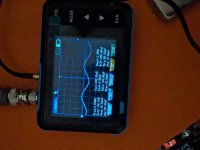
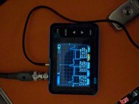
I've tried both cables going straight from the in and out to check the cables and turning the reverb knob and they both work. By testing it that way it does some phasing stuff to the sound which means the amp is definitely sending AND receiving signal through it as well.
Yet somehow it doesn't work when I actually play through the tank. :(
It just makes no sense to me.
 
Put a 100uf capacitor in series with the signal coming out of the "reverb send" jack. Probe that output with the clip on the scope probe clipped to metal on the chassis.

Then send a 0.5V sine wave into the amp input and see what you get. If it's distorted, turn down the amp gain and see if it cleans up.

Random screw sticking out of the chassis underneath as ground. Cleans up around 3 for the clean channel gain. Frequency measurement jumps around more though. The 3 khz is basically an arbitrary measurement with how much it jumps
 

Attachments

  • PXL_20260519_043050665.jpg
    PXL_20260519_043050665.jpg
    218.1 KB · Views: 3
  • PXL_20260519_043410792.jpg
    PXL_20260519_043410792.jpg
    542.8 KB · Views: 3
  • PXL_20260519_043418783.jpg
    PXL_20260519_043418783.jpg
    537.3 KB · Views: 3
On the reverb tank my multimeter measures it as 24 ohms input, 201 ohms output, but transducers don't measure accurately like that anyway. Just reflowed it for shits and gigs even though I've checked the connections before multiple times.
 

Attachments

  • PXL_20260519_050024612.jpg
    PXL_20260519_050024612.jpg
    500.5 KB · Views: 3
  • PXL_20260519_050016818.jpg
    PXL_20260519_050016818.jpg
    488 KB · Views: 3
Have you tried cleaning all the contacts? I used to own a VH140c and it just needed a good cleaning to get back to normal when I got it. It’s an old ass amp.
Hey I was exploring the forums and saw you might still have a ss140c (or had one in2021 so fairly recently). If you still have that could you check which reverb tank it has? It probably uses the same reverb tank as the vh and I don't think my reverb tank is the original and can't seem to figure out what they are supposed to use.
 
Hey I was exploring the forums and saw you might still have a ss140c (or had one in2021 so fairly recently). If you still have that could you check which reverb tank it has? It probably uses the same reverb tank as the vh and I don't think my reverb tank is the original and can't seem to figure out what they are supposed to use.

Sorry man, she gone. 😂
 
I was one of the very few PA area St. Louis Music repairman from the 80's to 2000's. It has been a long time since I have seen an Ampeg SS-140C, which is the predecessor to the VH-140C (they are essentially the same amp, sans a few changes in select components). I still have all the schematics.

The correct reverb tank for this amp would be the SLM part number 79-214-02. The conversion to the Accutronics equivalent would be 8BB2A1B.

As @Aentons stated, the tanks in the Type 4 series most common with tube amps having an 8-ohm input would have an impedance mismatch with the VH-140C or the SS-140C. Most of the energy from the 'send' circuit would be sent to signal ground instead of as energy into the reverb springs.

Hope this helps.
You sure the equivalent is an A with a grounded input and not an ungrounded C like he already has?
 
The correct reverb tank for this amp would be the SLM part number 79-214-02. The conversion to the Accutronics equivalent would be 8BB2A1B.
Hell yeah appreciate it!

You sure the equivalent is an A with a grounded input and not an ungrounded C like he already has?
Good question. I checked the amps rca jacks themselves and both are grounded. From what I'm googling that means that the tank itself is supposed to have the input isolated to prevent ground loops when the amps jacks are grounded if I understand correctly?
 
If it is supposed to be a C then my tank should be good. It measures, it smacks both ways etc... So unless I needed the A then it seems it's time for me to start cracking open the amp and trying to check all the test points.

It was open when I got it split into a head and a cab (broken shell where the front speaker baffle was only connected on one side, etc..) and we didn't see anything obviously wrong in there. No busted caps, burns etc.. I told them to let their tech buddy take a look to fix the reverb but they didn't because the smack test worked..... Didn't even play through the thing I guess. It's almost like I told them the reverb didn't work for a reason! Who'd've thunk. It's so typical that people always think they know better.
The tolex is lifting all around at the ends too. :( Can't decide if I should take their logo off the cab because they don't deserve the advertisement, or if I should leave it on and let the tolex keep peeling so that their work can speak for itself.
 
Last edited:
It's a split back so I can go open or closed back. Got some black shadows in there with it open. 🔥 It fills the room so much for a 2x12.
But all the complaining is beside the point.
 

Attachments

  • PXL_20260506_024421482.jpg
    PXL_20260506_024421482.jpg
    467.7 KB · Views: 5
  • PXL_20260506_024415137.jpg
    PXL_20260506_024415137.jpg
    266.2 KB · Views: 5
  • PXL_20260506_024705293.jpg
    PXL_20260506_024705293.jpg
    430.4 KB · Views: 5
Last edited:
The correct reverb tank for this amp would be the SLM part number 79-214-02. The conversion to the Accutronics equivalent would be 8BB2A1B.

You sure the equivalent is an A with a grounded input and not an ungrounded C like he already has?

Based on this schematic posted earlier, assuming it's the right one, the send side has a 47 ohm resistor between the sleeve and "chassis ground". The return side sleeve is connected to "circuit ground". This should mean the reverb tank itself needs to be input ungrounded, output grounded.
Untitled.jpg
It's odd that there's such a complete schematic and build doc available yet it doesn't specify what reverb tank. At least I couldn't see anything about it in there.

44V through a 330 ohm resistor makes it look to me, in my personal opinion, like it's for a higher impedance tank. 44V is a lot of headroom for voltage swing, which is what you want for higher impedance tanks. Although it could just be a way to limit the voltage/current into 150 ohms, seeing as the resistor is spec'd at 10W. They were probably just designing for whatever tank was common/available/cheap at the time and what voltage was available from the power supply. Just thinking out loud here.

For reference, a lot of amps use a drive circuit like this:
Unt.jpg
Which is intended for an 800 ohm 8EB2C1B, running the opamp off +/-15V.

If it was my amp I'd check the components in the drive section. Seems like you should be getting a quiet little bit of reverb even if the impedance isn't optimum.* I'd look at the two transistors and the 330ohm resistor first.

*If you want I'll try plugging an incorrect 150 ohm tank into my combo amp expecting 800 and see if it's still audible at all. I've tried it the other way before, a 150 on a circuit expecting 8 and since it's current drive it overdrives it and distorts like crazy.
 
*If you want I'll try plugging an incorrect 150 ohm tank into my combo amp expecting 800 and see if it's still audible at all. I've tried it the other way before, a 150 on a circuit expecting 8 and since it's current drive it overdrives it and distorts like crazy.
hell yeah I appreciate all of that! From my understanding, if it wanted an 800, a 150 would get driven too hard right? And you said the input is supposed to be isolated on the tank like it is. So yep time to open the amp.
 
hell yeah I appreciate all of that! From my understanding, if it wanted an 800, a 150 would get driven too hard right? And you said the input is supposed to be isolated on the tank like it is. So yep time to open the amp.
If the circuit is current drive it should actually drive a lower impedance less hard. I'm not completely sure if it is though.
The thing I want to check is if using a 150 ohm in my combo amp will be so quiet as to be inaudible.
 
You sure the equivalent is an A with a grounded input and not an ungrounded C like he already has?
Yes, again according to SLM specs. SLM often did not connect the return braid of the coax cable to ground, hence it receiving its ground shielding from the tank chassis. SLM also liked to have parts common across its products. Hence if 79-214-02 reverb tank was the 'chosen', it got used in everything with a tank reverb, even if there were more suitable components.

No, if I were designing the proper tank for that amp. I'd choose the input to be grounded to the tank chassis and the output to be isolated from the chassis and the cables to get its ground from the signal ground path.
 
Yes, again according to SLM specs. SLM often did not connect the return braid of the coax cable to ground, hence it receiving its ground shielding from the tank chassis. SLM also liked to have parts common across its products. Hence if 79-214-02 reverb tank was the 'chosen', it got used in everything with a tank reverb, even if there were more suitable components.
Gotcha so my C should be fine since I'm using fully connected cables. It's just that Ampeg originally used grounded A's on everything but lifted the ground on the cable instead as needed?
 
Back
Top