Love My Switches 3DPT Boards

maracarbonara

New member
Hey guys, I'm working on a procrastinator kit and I have a bunch of 3PDT boards from love my switches I would like to use up but I'm a little confused how to integrate it into this kit, particularly where to solder SW but honestly a little uncertain about the whole thing. Can I leave the LED off the main board and move it to the switch board? What would I hook v+ to?

1000012916.png
 
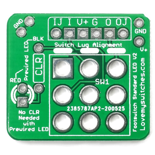
I have LMS's pre wired LEDs so the resistor is already taken care of. Just to make sure I'm following, I can jump the - from the main board's LED spot to the pad just below where CLR is marked? For the positive side it looks like it traces back to v+, so nothing else should be needed right?
 
If that's the case, you can install that led at any of the 4 CLR or LED pads, whatever is cleanest and easiest(mind polarity, whichever side goes to SW is negative, V+ is positive) then jumper the remaining 3 pads.
What happens at the daughter board/3pdt is the connection to ground is switched. The led is always connect to V+.
In your situation, the path is CLR, led pad, SW to V+, daughter board CLR, daughter board led pad, 3pdt switch, ground pad.
 
I prefer the PPCB breakouts, but the LMS ones have some cool hook ups. Extra power and grounds. They are useful and I think the members here solved this for you I hope. I was confused with it also.
 
1000013171.jpg

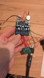
So I *think* I followed the advice I got here but running into issues. Guitar signal passes through when pedal is off, when the switch is depressed I have no LED and I get a weaker guitar signal with no effect. What did I miss?
 
On the LMS board, across the top

IJ is Input jack, the lead coming from the input
I is In, which goes to the IN on the PPCB board, the one on the far left
V+ is just a positive voltage source, which is usually the same as SW on the PPCB board
G is ground
O is Out from the PPCB board
OJ goes to the output jack.

It looks like, if you are using the LED clr on the PPCB board, then you can just wire a regular LED across the +, or RED solder hole, and the BLK, the upper hole of the LMS board's CLR resistor.

From your pic, assuming the Fender cable goes to your amp, you do have the breakout board wired up correctly and your problem is on the PPCB board itself. You can verify this by wiring the signal from the in and out jacks directly to the In and Out on the PPCB board.
 
The sw usually goes to ground, so if the led on the stomp is being used, then, if I’m seeing this right, the main clr should be jumpered since there’s one on the stomp board. If the main board clr is being used, then the stomp board clr should be jumpered. That should fix the LED issue.
 
Back
Top