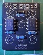
I was working on building an El Sol Distortion pcb when I noticed that there are only 5 spots for capacitors on the pcb. The parts list calls for 6 of them. The missing cap spot on the pcb is a 4n7 film cap. Should I be worried? Did they change the pcb and not update the schematic? Thanks in advance!

You are using an out of date browser. It may not display this or other websites correctly.
You should upgrade or use an alternative browser.
You should upgrade or use an alternative browser.
El Sol Distortion PCB is different than the schematic
- Thread starter kirt1974
- Start date

owlexifry
Well-known member
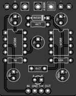
the 4n7 cap goes here:The missing cap spot on the pcb is a 4n7 film cap

Erik S
Well-known member
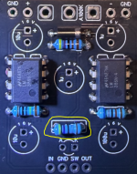
Looks like maybe you put a resistor where that cap was supposed to go (lower middle).
Also looks like your ICs might be upside down.
Also looks like your ICs might be upside down.
A little.Should I be worried?
owlexifry
Well-known member
Also looks like your ICs might be upside down.

owlexifry
Well-known member
absolutely have.Sorry for laughing at your pain @kirt1974 - we’ve all been there.
just as well they're only 8 pin.
[16 pin is pure masochism when your solder sucker is a POS]
yep.those ICs will be a challenge.
@kirt1974
- use flux.
- have a good solder sucker.
- expect it to take a long time.
if all else fails, and you're able/prepared to sacrifice the ICs, you could just snip them off and then suck out the remaining legs one by one.

Just for clarification: does the little circular indentation on the IC indicate the direction the IC should be oriented? Should the indentation face the little notch on the IC that’s printed on the pcb? I assumed that the text on the IC was supposed to indicate the orientation. I also assumed that the circular indentation was the spot where the plastic was injected into the mold at the factory. I learn so many new things every day. Haha!
Erik S
Well-known member
Just for clarification: does the little circular indentation on the IC indicate the direction the IC should be oriented? Should the indentation face the little notch on the IC that’s printed on the pcb? I assumed that the text on the IC was supposed to indicate the orientation. I also assumed that the circular indentation was the spot where the plastic was injected into the mold at the factory. I learn so many new things every day. Haha!
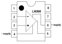
The dot indicates the location of pin#1. The pins are numbered counterclockwise.
Some DIP8 (Dual Inline Package, 8 pin) ICs have a dot, some have a little mouse-bite out of the top, some have both.
PPCB boards normally indicate the top (pin one end) with the indent on the silk screen.
Pros and cons of sockets are a matter of some debate around here, but personally, my ICs get mounted in these:
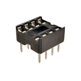
8 pin DIP IC Socket Adaptor Solder Type
GTK - Get It Fast - Same Day Shipping
 www.taydaelectronics.com
In the case of a wrong orientation, they make life a lot easier.

fav13andacdc
Active member
Yep! The circular indentation indicates the orientation. Top left. Some ICs also have their own notch in the top middle (like the outline on the PCB).Just for clarification: does the little circular indentation on the IC indicate the direction the IC should be oriented? Should the indentation face the little notch on the IC that’s printed on the pcb? I assumed that the text on the IC was supposed to indicate the orientation. I also assumed that the circular indentation was the spot where the plastic was injected into the mold at the factory. I learn so many new things every day. Haha!
It’s also common practice to add 8 pin sockets instead of soldering the ICs directly. Helps prevent situations like this!
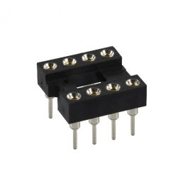
Edit: @Erik S is quick with it!
Thanks!!! I’m definitely going to order a bag of those sockets.Yep! The circular indentation indicates the orientation. Top left. Some ICs also have their own notch in the top middle (like the outline on the PCB).
It’s also common practice to add 8 pin sockets instead of soldering the ICs directly. Helps prevent situations like this!
Edit: @Erik S is quick with it!