
@bluedmc777's build report, Sheepy Love Bee Sting (One Control Silver Bee) brought this circuit to my attention. After reading the build report, I immediately went to Sheepy Love's Bee Sting Product Page so I could look at the schematic. I initially missed the numerous references across the main Sheepy Love site and the build doc that says this is a "Mods by HamishR" circuit. Most of the Bjorn Juhl overdrive circuits I've looked at use the wacky CA3130EZ single opamp plus a JFET for gain recovery. So looking at the Bee Sting schematic, I saw it uses a good ol' TL072. Still under the mistaken impression that this was a straight trace of the One Control Silver Bee, I thought perhaps Bjorn had abandoned the old architecture in this newer design.
So I copied the circuit into my own PCB. I'm working on a series of builds now to have explicit hardware references for my microcontroller bypass firmware. So with the PCB already designed and submitted to JLCPCB, I randomly took a break at work and was looking at threads on freestompboxes, when I ran across this thread: Bearfoot - Silver Bee Overdrive [traced]. This has the actual trace of the Silver Bee Overdrive, and @HamishR's commentary on the mods he did to the circuit! It was only then I realized the circuit I used wasn't the "real" Silver Bee, but the HamishR modded Silver Bee. I took that as a positive though, as I've enjoyed a lot of his mods (particularly when he collaborates with @Chuck D. Bones). In fact, his Old Fashioned has been a mainstay on my board since I built it.
So anyway...
This one's for you, Don!
After building it up, on first power-on, bypass worked fine, but I got nothing when I engaged the circuit. I first suspected the bypass scheme, since this was my first build with this particular scheme, and first live test of the MCU firmware. But I triple-checked the bypass wiring, verified switching voltages, and manually ran through the switching logic table for the 100th time. I felt pretty confident the switching was right. More on that later.
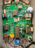
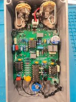
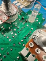
So I busted out the audio probe and found everything seemed right until the last coupling cap between the effect's last opamp output and the volume control. This is a 1uF film cap. It's certainly possible that I got a bad film cap, but it seemed unlikely. But, I went ahead and un-soldered the cap. Before soldering in a new one, I checked continuity between the cap's solder pads and the neighboring components: one side in fact did not have continuity. I didn't scratch the PCB; and it's a straight and very short trace (about 1cm). I tested the same trace on one of my unpopulated boards - it was fine there. So I'm not sure if I somehow damaged the trace during initial assembly, or if this one board happens to have a manufacturing defect. Either way - I replaced the cap, and left a little extra lead length to use as a fix for the apparently bad trace. See the picture below.
Once I got that sorted out, it worked. But the next problem: the switching made a pretty awful "pop" whenever I changed between engage or bypass. Which is the exact opposite of what it should do: in my past usage of the CD4053 analog switch, I used a simple scheme, which sometimes did have a bit of pop. But in a DM conversation with @jubal81, he suggested a smarter way to wire the CD4053, which allows for an explicit mute state. Thus the circuit can be muted, then switched, then un-muted, resulting in pop/click free switching.
I spent a lot of time reviewing the schematic. First thing I noticed: I had a pulldown to ground resistor on the same net as where I had a pullup to VREF resistor. This wasn't a major problem, but would affect the bias at that stage, reduces headroom, and wastes current. So I pulled that resistor. It didn't fix the popping.
I finally realized: my mistake was forgetting that, within the CD4053 sub-circuit, for the actual audio signals, "ground" is VREF. I was mistakenly using power ground (i.e. 0v plane) for muting. The dramatic voltage jump between 0v and 4.5v (VREF) was causing the popping. Rather than try to cut PCB traces, I just lifted the mis-routed 4053 pins out of the socket, and used a wire to tie them to VREF. Now it has truly pop-free switching!
After all that rigmarole, it turns out I'm not terribly hot on the circuit. Not that it's bad by any means! It's a great-sounding circuit. But I prefer this Barber Silver LTD clone I've been rocking for a few weeks now. Comparing the two, the Silver Bee feels a bit "softer", while the LTD is "crisper". Again - not bad, this just speaks more to my preferences than the circuit quality. The next guy might have the exact opposite opinion.
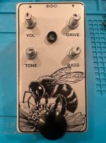
The enclosure actually came out pretty nice. I recycled the graphic from my Aion Procyon, this time on a Tayda "Ball Silver" enclosure. (Ball Silver for the Silver Bee circuit, get it?)
So, despite not being thrilled with the effect itself, it was a good learning experience, and ultimately does prove out one aspect of my MCU firmware / bypass design scheme.
So I copied the circuit into my own PCB. I'm working on a series of builds now to have explicit hardware references for my microcontroller bypass firmware. So with the PCB already designed and submitted to JLCPCB, I randomly took a break at work and was looking at threads on freestompboxes, when I ran across this thread: Bearfoot - Silver Bee Overdrive [traced]. This has the actual trace of the Silver Bee Overdrive, and @HamishR's commentary on the mods he did to the circuit! It was only then I realized the circuit I used wasn't the "real" Silver Bee, but the HamishR modded Silver Bee. I took that as a positive though, as I've enjoyed a lot of his mods (particularly when he collaborates with @Chuck D. Bones). In fact, his Old Fashioned has been a mainstay on my board since I built it.
So anyway...
Lol why is it unremarkable when a build goes as planned?
This one's for you, Don!
After building it up, on first power-on, bypass worked fine, but I got nothing when I engaged the circuit. I first suspected the bypass scheme, since this was my first build with this particular scheme, and first live test of the MCU firmware. But I triple-checked the bypass wiring, verified switching voltages, and manually ran through the switching logic table for the 100th time. I felt pretty confident the switching was right. More on that later.
So I busted out the audio probe and found everything seemed right until the last coupling cap between the effect's last opamp output and the volume control. This is a 1uF film cap. It's certainly possible that I got a bad film cap, but it seemed unlikely. But, I went ahead and un-soldered the cap. Before soldering in a new one, I checked continuity between the cap's solder pads and the neighboring components: one side in fact did not have continuity. I didn't scratch the PCB; and it's a straight and very short trace (about 1cm). I tested the same trace on one of my unpopulated boards - it was fine there. So I'm not sure if I somehow damaged the trace during initial assembly, or if this one board happens to have a manufacturing defect. Either way - I replaced the cap, and left a little extra lead length to use as a fix for the apparently bad trace. See the picture below.
Once I got that sorted out, it worked. But the next problem: the switching made a pretty awful "pop" whenever I changed between engage or bypass. Which is the exact opposite of what it should do: in my past usage of the CD4053 analog switch, I used a simple scheme, which sometimes did have a bit of pop. But in a DM conversation with @jubal81, he suggested a smarter way to wire the CD4053, which allows for an explicit mute state. Thus the circuit can be muted, then switched, then un-muted, resulting in pop/click free switching.
I spent a lot of time reviewing the schematic. First thing I noticed: I had a pulldown to ground resistor on the same net as where I had a pullup to VREF resistor. This wasn't a major problem, but would affect the bias at that stage, reduces headroom, and wastes current. So I pulled that resistor. It didn't fix the popping.
I finally realized: my mistake was forgetting that, within the CD4053 sub-circuit, for the actual audio signals, "ground" is VREF. I was mistakenly using power ground (i.e. 0v plane) for muting. The dramatic voltage jump between 0v and 4.5v (VREF) was causing the popping. Rather than try to cut PCB traces, I just lifted the mis-routed 4053 pins out of the socket, and used a wire to tie them to VREF. Now it has truly pop-free switching!
After all that rigmarole, it turns out I'm not terribly hot on the circuit. Not that it's bad by any means! It's a great-sounding circuit. But I prefer this Barber Silver LTD clone I've been rocking for a few weeks now. Comparing the two, the Silver Bee feels a bit "softer", while the LTD is "crisper". Again - not bad, this just speaks more to my preferences than the circuit quality. The next guy might have the exact opposite opinion.
The enclosure actually came out pretty nice. I recycled the graphic from my Aion Procyon, this time on a Tayda "Ball Silver" enclosure. (Ball Silver for the Silver Bee circuit, get it?)
So, despite not being thrilled with the effect itself, it was a good learning experience, and ultimately does prove out one aspect of my MCU firmware / bypass design scheme.
Attachments
Last edited: