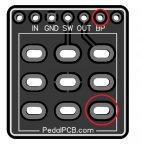
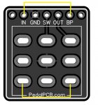
The Input jack is always connected to the In pad on these, it isn't switched.
It would take several jumpers to use this in a true-bypass effect, you'd be better off just wiring up the effect with it out...
You would need to:
Connect the input jack directly to the center lug of the left column of the switch
Connect a jumper from the In pad to the top lug of the left column of the switch
Add a jumper across the two bottom outer lugs of the switch (shown in yellow in the post above)
Wire up GND/SW/OUT and the output jack like normal, ignore the BP pad.