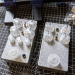
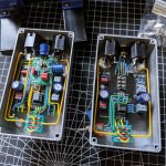
A pair of Tommy III's, plus a lil' extra.

junderwood

Active member
After getting a little help over in the General Questions forum I finished up this awesome pair of Tommy III's. I routed the internal symmetric/asymmetric switch to the outside on both and also added a Rullywow Serpent Boost to one of them just for something a little different. These things sound excellent, and were a ton of fun to build. These were my first two DIY pedals but certainly won't be my last :D
 

Attachments

  • timmy1.jpg
    timmy1.jpg
    240.5 KB · Views: 169
  • timmy2.jpg
    timmy2.jpg
    256.5 KB · Views: 171
🙀

When you say "first two DIY pedals", do you mean first PedalPCB builds, or do you mean first "two" but you've built plenty of "single" pedals before? Surely these aren't your first builds... I try to get my wiring to look like that, but it always looks more like a plate of spaghetti.

Man, that's just off the charts in terms of tidy wiring and the overall aesthetic of the builds. As someone that always crams too much into too small a box, myself... the extra Rullywow stuffing is awesome.

Into my Pedal Inspirations folder they go!
Wow, thank you! I sort of expected gentle chiding at my lack of heat shrink and component usage. These are the first two guitar pedals I've built, but I have done other stuff that's more complex in the past, like 500 series kits and designed/built mechanical keyboards. The wiring method I used was just to grab some solid core hookup wire I had laying around cut it a little longer than I thought it should need to be, then bend at mostly right angles until it fit like a puzzle piece. Then soldered it in place. I need more than three colors in the future though, lols.

If you're curious, here's what they sound like (more info on signal path is in the description):
 
Very clean wiring. My builds never look that good--which is why I'm happy the wiring is covered up.
Thank you! I've seen a pedal somewhere with a clear top on it so you could see the guts... The PedalPCB pcbs are so pretty, I bet they would look good like that as well.
 
OK, now I remember.

SW2 connects C9 and R12 into the circuit in either the UP or DOWN position, I don't have a board so I don't know which it is. You'll have to figure that out with a DMM. For the sake of discussion, let's say it's the UP position that connects C9 and R12. An ON-OFF-ON switch will disconnect them in both the CENTER and DOWN positions. The CENTER position will do what the DOWN position used to do and the DOWN position will do something new.

You have some options for what you want that "something new" to be.
Suppose you want the extra position to increase the gain, but not increase the bass. Find which switch terminal connects to R12 (I'm guessing it's 3) and jumper terminal 3 to terminal 1.
Or suppose you want the extra position to increase the bass, but not increase the gain. Find which switch terminal connects to C9 (I'm guessing it's 6) and jumper terminal 4 to terminal 6.
Obviously, you would do only one of these, not both.

If you want to get fancier, skip the jumper and connect a different value cap between terminal 6 and Vref. Or connect a different value resistor between terminal 3 and pin 3 of the GAIN pot. Or do both the resistor and the cap.

Again, I'm guessing which switch terminal goes where, you will need to break out the DMM and measure the continuity to verify which switch terminal goes where.
 
Thank you so much. How about the 100pf cap? how many volts is that one? And why don't they put this information in the instructions on the parts list lol?
you would think that its kind of relevant right lol
 
Normally you don't have to worry about pF & nF range caps as they are usually minimum of 50V rated which covers any pedal we do. Just the Electrolytics you have to check are a high enough voltage rating for the voltage used x 2 to power the pedal
 
  • Like
Reactions: fig
Back
Top