You are using an out of date browser. It may not display this or other websites correctly.
You should upgrade or use an alternative browser.
You should upgrade or use an alternative browser.
SOLVED Abyss rate led stuck on
- Thread starter cniers13
- Start date
Are you still getting the rate function to work (hearing modulation when you change the setting on the pot)? I was asking to see if the problem is that the LFO is not working, or if it is only the LED that is stuck in the "on" position. when the title is "abyss rate LED stuck on" it could mean either one of those situations.
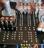
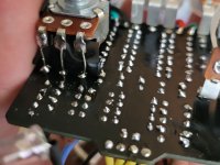
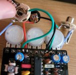
Take a close look at the wires coming into the board from the footswitch to make sure there are no accidental shorts. Also look at the connections for the dual rate pot (can't see the inner ones in the pic). since the rate control worked and then stopped working it is likely a bad solder joint or a shorted contact in the LFO section. what voltages are you getting on the transistor? do they change when you adjust the rate pot or the depth/intensity pot?
Chuck D. Bones
Circuit Wizard
When you say "rate LED," you mean the LED in the middle of the LDR huddle? There is no Rate LED per se.
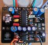
I do not recommend using aluminum electrolytics for C11 - C13 (especially C11). They are leaky and can stop the LFO. Use tantalum. Film would be better, but good luck fitting a film cap onto that footprint.
Measure the voltage on Q1-C.
I do not recommend using aluminum electrolytics for C11 - C13 (especially C11). They are leaky and can stop the LFO. Use tantalum. Film would be better, but good luck fitting a film cap onto that footprint.
Measure the voltage on Q1-C.
Chuck D. Bones
Circuit Wizard
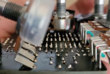
The voltage on Q1-C should move around at the LFO freq. If it's not, then the LFO is definitely stuck. Since it was working and now it's not, the most likely suspects are a bad solder joint & conductive debris. Inspect everything, especially around the SPEED pot, R17-R22, Q1, C11-C14. Use magnification and plenty of light. Have you removed & replaced any parts during the build?