Kroars
Well-known member
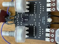
Built my fourth Acid Rain (love that circuit!) and I’m having a little trouble with it. Plugged it in and noticed that I can only hear the effect faintly when volume and gain fully CW. Bypass works great. I probed it and while one side of C3 (470p) is much quieter on the probe (unlike the working one I tested) everything else seems to check out. I replaced c3 just in case but same issue persists. Even got a signal going from input to output jack when effects on with the probe. Started taking voltage readings and noticed that Q1 & Q2 have 0v at collector. Q3 has 4.5v and Q4 has 5v. I’m stumped and really hoping someone can nudge me in the right direction.
50% of resistors were tested and all caps and transistors were tested prior to installation. Also tested volume pot and gain pot while in the circuit and both go from 0 to 100 just fine.
Hope everyone is having a great Saturday!
50% of resistors were tested and all caps and transistors were tested prior to installation. Also tested volume pot and gain pot while in the circuit and both go from 0 to 100 just fine.
Hope everyone is having a great Saturday!
Attachments
-
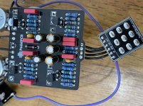 9A218733-60F6-4876-9283-50A11F78B95E.jpeg338.8 KB · Views: 7
 -
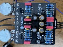 F3529215-BE5D-4F4F-B957-8D9439B73E3C.jpeg327.7 KB · Views: 7
 -
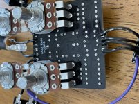 800D25A4-FD45-4448-958D-220105138BF8.jpeg349.3 KB · Views: 6
 -
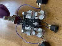 94967FAD-F7FE-47CF-8547-766F49780DA1.jpeg434.3 KB · Views: 6
 -
 FCC9DD40-ACF2-4A9B-92C4-D82E77D4DB50.jpeg287.8 KB · Views: 6

