Add a little boosting to the opamp buffer

gkgkgkrj

New member
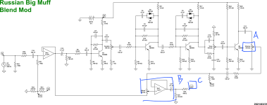
It's a circuit related to signal blending using opamp

In A, we amplify the signals from opamp-2 to control the volume

In B, when combining signals, A adjusts the volume separately, so the blending ratio keeps changing according to the volume of A, so I'm going to modify this circuit

I want to change A to fixed resistance and adjust some boosting and control volume in C
Is there a circuit or way to refer to it???
 

Attachments

  • KakaoTalk_Image_2024-06-11-15-45-19.png
    KakaoTalk_Image_2024-06-11-15-45-19.png
    271.4 KB · Views: 10
I'm not sure if you're just working off a schematic or a PCB. I will assume you've just got a schematic and will make PCB/stripboard separately.

The control for A is merely a voltage divider. Turning the knob alters the values of R1 and R2 below between 0 and 100k ohms. This is an easy way to experiment on a breadboard.
1718105304873.png

For C, you can see that R30 and R37 form a voltage divider like the screenshot above. You can swap a potentiometer for the two (100k).

For B, you can do 1 of 2 things IMO. You can either keep the topology (non-inverting opamp buffer) and add a few components to make it amplify. Below is an example from the Dist + circuit. You can alter the values of R2 and R3 to set the gain (boost). R3 and C3 select the frequency to boost. You will need to bias the opamp by adding R5 in the below.

Edit: Now that I think this through, you COULD keep the GAIN control in the below and that will be your overall volume control instead of your C section highlighted above, but I would use a lower value pot (500k or below).
1718105732519.png
The alternative (fewer parts) is to make it an inverting opamp gain stage, but you'll need to change which pin the signal goes into. Your schematic above has it going into the non-inverting input (+) and you can change it to the below. This is taken from the Mini-Muffin fuzz schematic. R3 and R2 ratio controls the gain (boost) and will boost all frequencies that are allowed in (there should be a capacitor right before R2 below). You will still need to bias the opamp with 1/2 voltage (VREF below).

1718105903819.png

Hope this helps.

BuddytheReow
 
Last edited:
2 ways I see.
1)Change a to A pot to a fixed resistor .
Move output pot to R30.

Or what I would do,
2) same as above PLUS change B blend pot to a MN taper pot.
The reason I would go this route is it offers no load on you clean signal until past the center point. This will be beneficial as your clean signal I likely lower level that your dirt signal.
My .02. good luck!
 
Back
Top