Aion Draco (Dr Boogie) JFET Bias

faramir

Member
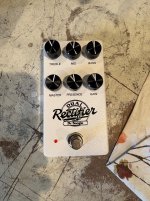
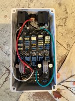
Built an Aion Draco Dr Boogie clone. Only issue I ran into was biasing the 4th J201. I could only get it to 5.8v with the trimmer turned all the way up. The others all could easily get 4.5v. Any ideas on why this might be? My guess is a bad J201, possibly damaged by me during install? I used a soldering iron at 700 deg F and they are SMD's installed straight to the board by me. I got them from Stomp Box Parts. Not sure how easy they are to damage or how they would behave if I did.

Despite this it actually sounds pretty good though its a bit staticky-fizzy sounding at some settings. Hoping fixing that bias issue will help. Definitely sounds better at 18V (I did the bias at 9).
 

Attachments

  • IMG_4595.jpeg
    IMG_4595.jpeg
    1.2 MB · Views: 17
  • IMG_4596.jpeg
    IMG_4596.jpeg
    1.1 MB · Views: 17
could only get it to 5.8v with the trimmer turned all the way up. The others all could easily get 4.5v. Any ideas on why this might be?
sometimes this just happens.
recently, ive breadboarded a JFET distortion circuit which also called for 50K trimpots, but i found one of the JFETs couldn't achieve a bias range that i was satisfied with. so i just swapped the 50K trimpot for a 100K trimpot. this solved that issue.

i suspect (guess) if you tried a 100K trimpot for that position you'd be able to bias it down lower.

sounds pretty good though its a bit staticky-fizzy sounding at some settings.
try it into the FX return of the amp to bypass the preamp (usually sounds better this way)
Definitely sounds better at 18V (I did the bias at 9).
agreed.
 
i can't get Q2 to bias and i've tried 3 different J201's (pcb mounted type).

Swap Q1 and Q2 and see if the problem changes location, if so, it's the transistor.

If not, check the value of the trimpot and the resistor from Q2 source to ground.

If the transistor biases properly in the Q1 location there's no reason it shouldn't bias similarly in Q2 unless one of the surrounding component values is incorrect.
 
got it to bias up perfectly, but overall it has VERY LOW signal. i can hear that all of the knobs are working but it has almost no output. i'll just have to go over it and find out where the problem is.
 
I know it sounds like beating a dead horse, but have you verified all resistor values to be correct? It can be easy to mistake a 10K with a 100K if you aren't paying enough attention. It's a mistake that I've made a handful of times and I'm sure it will happen again.
 
Swap Q1 and Q2 and see if the problem changes location, if so, it's the transistor.

If not, check the value of the trimpot and the resistor from Q2 source to ground.

If the transistor biases properly in the Q1 location there's no reason it shouldn't bias similarly in Q2 unless one of the surrounding component values is incorrect.
I pulled the transistor, will swap it out. Need to order some more though. Thanks.
 
got it to bias up perfectly, but overall it has VERY LOW signal. i can hear that all of the knobs are working but it has almost no output. i'll just have to go over it and find out where the problem is.
well, replying to my own post, i still can't can't hardly any output form the circuit and i've checked the connections and my soldering multiple times.
 
Back
Top