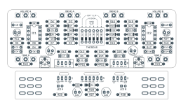
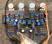
Aion Fx Theseus issues - King of tone

eurobailey

Active member
I built the aion fx KOT about 4 years ago and its been the bane of my pedal building journey!!!

The first time my issue was a solder bridge on the switch. Once fixed, the pedal worked however on side B i get the boost and drive settings but not the distortion setting. On Side A i get all three settings working as they should.

My tests so far have been checking FV of the diodes in circuit (no power) to ground and they seem ok. The hard clipping diodes are 1n914 in my build.

I have also checked continuity between the diodes and the switch. So i get continuity with the switch UP or DOWN with the respective diodes.. which seems incorrect however i get this on Side A and B and have no issues with Side A?

i am assuming i have a faulty switch or a solder bridge somewhere but i am a bit stumped as what my next move should be? Would love any suggetions.

Today I unsuccessfully tried to remove the dip switch… I will try again tomorrow but also wondering what else I can try to get this to work ? Someone suggested running a wire on both sides of the “hard clipping “ switch to permanently have the diodes in the circuit but this didn’t seem to have any impact.

I am using Revision A from aion FX. This is the schematic.

 
I can't see anything wrong from the pics you've provided..
apologies, i havent provided photos as in this case i wasnt sure it would help. The pedal is working apart from the distortion so its not a wiring issue. I guess i am trying to track down what i can test to see if its a switch failure. I am not sure. a photo will show a damaged trace for example and often it just promotes commentary around adding more / less solder etc (not saying that is not an issue, but i am trying to understand the circuit more to be able to test areas that might reveal my issue).
 
Connect the switch to GND instead of the diodes. The signal should drop out when you flick the switch. It would show the switch working.
I always found the dist to be mildly different at best.
 
Connect the switch to GND instead of the diodes. The signal should drop out when you flick the switch. It would show the switch working.
I always found the dist to be mildly different at best.
That’s a great shout thanks.

Yeah I think it’s half the reason I didn’t get this pedal ! I always expected the distortion setting to be “distorted” it’s a hair more gain. The only way I really worked it out is people said you will get a volume drop for each setting, from boost.. to drive to distortion.
 
The Sheepylove Kaiser (Chuck's Emperor of Tone) has the dist blend on a pot, and there is a difference but you have to question whether it's worth the cost of a pot :D

Another thing to try is a boost in front. Get a bit more signal, which should distort a bit more.
 
The Sheepylove Kaiser (Chuck's Emperor of Tone) has the dist blend on a pot, and there is a difference but you have to question whether it's worth the cost of a pot :D

Another thing to try is a boost in front. Get a bit more signal, which should distort a bit more.
yeah my main thing thats annoying me with this build is that on side B i am getting no distortion at all. Its literally the boost setting. With the soft clip i get the over drive setting. Side A it all works. I will do what you suggested tomorrow and see how i go.
 
So, bad news i. guess! i have taken the pcb out of the enclosure and connected it up to my test pedal. Side A (that works) when i shunt the hard clip to ground with the switch up, the effect goes silent (as expected). When i do the same to Side B (that isnt working) and shunt the hard clip to ground it also goes silent....... Which means the switch is doing what it should??? The only thing that seems weird... is that for the soft clipping diodes (when i shunt them to ground, with the switch down, and i touch the top part of the switch, it goes silent as well? shouldn't it only do this when the switch is up?

yes the Switch A (looks low on solder) that had issues earlier and now rectified. The board itself looks a bit covered in flux, when i built this i was having issues with my solder iron (there was a hole in the tip! that i wasnt aware of) i could give the board another clean. If the switch is operational, what else can i do to try get those diodes in circuit to see that are working?

Screenshot 2026-09-09 at 8.13.45 am.png Screenshot 2026-09-09 at 8.30.40 am.png
 
Are you SURE C15 is ok? It does not take much melting damage to ruin one of these caps, you'd need to isolate (remove) it and test it to be sure it's good. At that point might as well replace it if you have another one.
 
Are you SURE C15 is ok? It does not take much melting damage to ruin one of these caps, you'd need to isolate (remove) it and test it to be sure it's good. At that point might as well replace it if you have another one.
I actually fried that trying to remove the dip switch!! So the issue was prior to that happening but yes , I should replace that. Good spot!
 
I mean this as constructively as possible. That is a rough solder job. Whether it's a cold join or an unintentional bridge, or something else, there could be lots of potential problems here. Volume A is pretty much a case study in bad solder joints.

Give the board a good cleaning with isopropyl and an old toothbrush. Try as gently as possible to reflow any joints that don't look like a Hershey Kiss. Break out your audio probe (build one if you don't have one). Failing those steps, might be time for the scrap heap.
 
I mean this as constructively as possible. That is a rough solder job. Whether it's a cold join or an unintentional bridge, or something else, there could be lots of potential problems here. Volume A is pretty much a case study in bad solder joints.

Give the board a good cleaning with isopropyl and an old toothbrush. Try as gently as possible to reflow any joints that don't look like a Hershey Kiss. Break out your audio probe (build one if you don't have one). Failing those steps, might be time for the scrap heap.
agreed with the soldering and the cleanup.... A careful reflow, good quality Solder wick and some 99% isopropyl could help get it sorted a bit better. This is a intermediate level build with a beginner level solder job.. That's ok.. we were all there and have to learn somehow. You have a lot of inconsistencies .. some need reflowed and some have entirely too much solder.. it all has flux that needs to be brushed and washed off.
 
I've had two Aion PCBs with defective solder traces, on their MT10 clones.

I suggest you use a DMM set on resistance and beep and check for continuity between the DIP switch points (testing the switch itself) and then point to point through the path of the diodes. Replace the switch if you find it does not work, and jumper any 'open' circuit traces.
 
I mean this as constructively as possible. That is a rough solder job. Whether it's a cold join or an unintentional bridge, or something else, there could be lots of potential problems here. Volume A is pretty much a case study in bad solder joints.

Give the board a good cleaning with isopropyl and an old toothbrush. Try as gently as possible to reflow any joints that don't look like a Hershey Kiss. Break out your audio probe (build one if you don't have one). Failing those steps, might be time for the scrap heap.
Yep - it looks pretty bad. This was one of my earlier builds and the iron I was using (unknown tk me ) had a hole in the tip… I remember at the time it was hard work getting solder to flow! Will clean it up, reflow side B and check for do some continuity checks and see where I end up
 
i just spent hours on this.... i gotta admit i prefer tagboard for trouble shooting! I couldnt for the life of me remove the switch, and it is showing continuity between ground and the diodes so i dont think this is the issue. I cleaned the board, reflowed a few joints, snapped a few wires connecting the main PCB and the 3dpt board.... this was a nightmare to try and remove the solder and stranded wire..... i redid all the wires and i am back to the start.... I also tried to remove the burnt cap, but even adding solder to the old solder, didn't really make the old stuff budge!

All the settings work apart from hard clipping on side B. Perhaps i just re box and move on but if anyone has any tips to try i would love to hear them.
 
Last edited:
Sometimes sticking through one to the end is worth the learning experience. I try the normal things like reflowing, inspecting closely and then break out the audio probe.... If I'm still baffled I will generally build another of the same board methodically just to have some closure. About 1/2 of my duds... which are fairly rare, never get resolved.. I just cut my losses and build another board out.. Typically I'm building for someone else and I have trust issues with boards I may have made a mistake on..
 
i just spent hours on this.... i gotta admit i prefer tagboard for trouble shooting! I couldnt for the life of me remove the switch, and it is showing continuity between ground and the diodes so i dont think this is the issue. I cleaned the board, reflowed a few joints, snapped a few wires connecting the main PCB and the 3dpt board.... this was a nightmare to try and remove the solder and stranded wire..... i redid all the wires and i am back to the start.... I also tried to remove the burnt cap, but even adding solder to the old solder, didn't really make the old stuff budge!

All the settings work apart from hard clipping on side B. Perhaps i just re box and move on but if anyone has any tips to try i would love to hear them.
destruction tip: sometimes dealing with switches or multileg components it's best to destroy the switch with snips from the topside carefully so you can desolder one leg at a time... you'll be less likely to lift a pad from trying to heat the joint too much
 
Back
Top