BEHOLD! My Cepheid Build, made with science

Stickman393

Well-known member
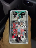
Whelp...it's not working quite yet. The LFO is active, but the clock chip is garbage. That'll teach me to try my luck on a cheap ebay deal.

Internals... Could be better. I've started using shielded input/output wires for pedals that have an LFO...I've had issues with ticking in a few builds, so I'm using some pushback wire. I'm maintaining a single point of termination at the ring of each jack by wrapping the shield in silicone tubing.

I'll be doing the same on my chaos machine build pretty soon...we'll see if this does the trick.

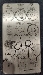
But...I'm quite happy with the way that the artwork came out though. Made with dihydrogen monoxide and sodium chloride.

Oh, as well as the power of electrons being ripped from their bonds and pulled through a subatomic raceway...

Yes. Electrolysis.

IMG_20210723_054512_60.jpg
IMG_20210723_054835_60.jpg
 
The time has come for the sequel.

Caesar, we hardly knew ye.

There are no fingerprints underwater
Nothing to tie one to a crime...

IMG_20210726_040853__01_80.jpg

I dunno. I may need to use a power supply with a little more oomph. The 30 water is a touch wimpy, and takes for friggin ever to get a good etch. Maybe invest in a Cricut machine and start using vinyl instead of iron-on transfers to mask the bare bits...

I'll probably get bored of etching eventually, but it works for now.
 
Last edited:
I've often wondered if someone could combine Shakespeare, electrolysis, laser beams, and a guitar pedal.

You sir have done it, twice! Very cool!

Be careful with that dihydrogen oxide! You know what happens if an extra oxygen molecule happens to take a shine to that good-looking hydrogen molecule over there! Dihydrogen dioxide. If that happens, throw in a potato and it will become a breath of fresh air and a beverage.

Did you fix your LFO?
Dihydrogen Dioxide! Gasp! Per-ish the thought!

Eh? Eh?

The LFO is good actually...the RATE led cycles just fine. It's just that the clock driver isn't exactly an MN3101. Not sure what it is, but it's being a poor foreman on the bucket brigade line.

Looks like I've got two replacements that will be arriving today...gonna be crossing my fingers here. If those are counterfeits as well, I've got an NTE1639 on the way too...I can't imagine anyone would actually counterfeit the AFTERMARKET repair part. But...I mean ...
 
  • Haha
Reactions: fig
I'm maintaining a single point of termination at the ring of each jack by wrapping the shield in silicone tubing.
Can you go into some further detail on that? I got two fun yet ticky pedals (Sea Horse and Chaos Machine), this seems like a nice fix.

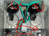
A - what's going on here? how to you split the tip/sleeve signals and send that to the board?
B - where is the sleeve signal going, if not in these spots?
C - bonus, love that you took these pics in your car, on your knee. ingenuity, scrappy and resourceful - qualities I've come to expect from @Stickman393

1627397163232.png
 
Can you go into some further detail on that? I got two fun yet ticky pedals (Sea Horse and Chaos Machine), this seems like a nice fix.

A - what's going on here? how to you split the tip/sleeve signals and send that to the board?
B - where is the sleeve signal going, if not in these spots?
C - bonus, love that you took these pics in your car, on your knee. ingenuity, scrappy and resourceful - qualities I've come to expect from @Stickman393

View attachment 14143

Happy to! Although with the caveat that I am no electrical engineer; I am but a simple HVAC mechanic. My understanding of some of these concepts might be a little...eh...inelegant.

In essence, I'm creating a faraday cage around my input and output signal wires.

The concept is a little heady, but for our purposes it's a means of preventing electromagnetic "noise" from effecting the electrons in a conductor.

This can be achieved by wrapping a conductor, or set of conductors, in a conductive braid or foil "shield". The shield alone doesn't do much though; by bonding the shield to ground at a single location, it's ability to absorb electromagnetic noise is greatly increased.

As an astonishingly inept metaphor, think of a boat in the ocean. The boat is your signal, the oceanic and atmospheric currents are electromagnetic noise, the shield is the anchor. Without the anchor, the boat gets pushed around all willy nilly, probably into the loch ness monster or something. If the boat drops anchor, but the anchor is, like, pitifully low mass, it will become dislodged and the currents *still* end up pushing the boat around. The boat's anchor ends up ripping through Nessie's home, making Nessie extra pissed off. Nessie munches on the boat whilst muttering something about humans being super inconsiderate.

BUT...if that anchor has sufficient mass, like if we connect the shield to ground, it's like loch Ness monster camouflage...thingie...I dunno, this metaphor has fallen apart.

Classic example: ever find that your cell phone signal goes to shit when you get into an elevator and the doors close? That's because you've walked into a faraday cage.

How bout a dumb example? When folks that are afraid of wifi buy a metal cage to go around their wireless router and then complain that their wifi signal has gone to shit on amazon reviews. Faraday cage.

Like I said...it's a heady concept, but it has multiple real world uses. That perforated screen in a microwave window? Part of a faraday cage. The outer conductor of a coaxial guitar cable? Faraday cage. Tin foil hat? Faraday cage.

Double espresso in a metal shot glass? Faraday café. I mean, I just made that one up, but why not?

HOWEVER, that part about connecting at a single point is important. Because when you create multiple paths to ground, you get ground loops. We really, really, really want to avoid ground loops because it renders our shield ineffective at best, counterproductive at worst. A big ground loop is basically an antenna.

Soooo...that's what I'm doing there. The shield is terminated at the ring, and isolated from the enclosure everywhere else. The inner conductor is terminated at the tip.

Truth told, those extra little connection points on the circuit board are redundant. A good real-world experiment: take your meter, set it to resistance, and measure between the negative input on an unpopulated board and one of those points. You will read close to 0 ohms, because they're common terminals. All three are connected via board traces, and therefore only ONE offboard connection is required. I suspect that the others are provided to help make enclosure wiring make more "sense" in a visual way, especially for people who are new to the hobby. It's a nice touch provided by pedalPCB.

Although...hmm...now that I think of it: It is possible to create a ground loop if the input/output rings are not isolated from the enclosure. In this case, two paths with differing resistance to the flow of electrons present themselves: one through the conductive enclosure, and one through the conductors that connect the ring terminals and the PCB. Huh.

That is true of the way that I have it wired as well...and I haven't really noticed any undue noise in my builds.

Anyways, that's a long preamble to the following: the "A" locations are simply my ground buss. As a daisy chain, it goes 9vdc pin -> output ring -> Input ring -> PCB. The B location is (red) to 9VDC barrel and (green) to input ring. The other two spots...well, they're already connected to my input and output jack via the single Green wire on my JST connector on my board.

And C...well...shucks. I'm just a dude, made from the same stuff as everyone else. You know. Sticks.

*Edited in a futile attempt for clarity*
 
Last edited:
Gavitt braided pushback wire is what I used, but that's only because I have a whole roll of the stuff. It's not super ideal for pedal builds due to the fact that the braid is unprotected and prone to making contact with everything...thus I used some 3mm ID/4MM OD silicon tubing I had laying around to protect it.

One last bit about faraday cages; they're no panacea. There are factors that l don't fully understand...thickness of shielding vs lengths of electromagnetic waves, something called skin depth I think...yada blah...

Other options...basically any 22-26awg coaxial cable - standard guitar cable tends to be too thick though. A miniature instrument cable would work well. Mogami W2314 is a good choice. Canare GS-4 as well.
 
"There's only 3 things I'm afraid of..." 😹


Question regarding ground loops...

Storyboardist from Effects Layouts often has a ground running around the edge of his perf layouts that's a complete full circle (not always, but often) —
So why doesn't this introduce some ground-loopage? For the layouts that don't have a fully circular ground, obviously it's not a loop. For the full-circle ones, once inside the enclosure the directional-antenna-effect is minimised, but what of the ground loop?
 
  • Like
Reactions: fig
"There's only 3 things I'm afraid of..." 😹


Question regarding ground loops...

Storyboardist from Effects Layouts often has a ground running around the edge of his perf layouts that's a complete full circle (not always, but often) —
So why doesn't this introduce some ground-loopage? For the layouts that don't have a fully circular ground, obviously it's not a loop. For the full-circle ones, once inside the enclosure the directional-antenna-effect is minimised, but what of the ground loop?
Gooooooooood question.

Listen, my schooling on electrical theory was pretty basic, most of the stuff past ohms law,
AC voltage, and inductive loads I've had to pick up over time by reading various articles across the internet. And I get things wrong...pretty often, truthfully. So I wouldn't take my word as the final on any of this...

But...as far as I know, several elements are required to create a ground loop: two points on the "ground" side of a circuit that are connected by two or more different paths with different resistances, and some outside force that creates a minor voltage difference between those two points.

But...a circular trace around the board...hell, I don't know. For that matter, what would be the difference between that, and the same trace but completely filled in?

...yeah...I don't know. Gotta do more reading.
 
I think you keyed it in with the 2-points differential (if I'm using the terminology correctly).

The circular point with the EL layouts is maybe moot 'cause the circle has but one point where it connects to the ground of the power jack; and of course the ground planes in a multi-tiered PCB as another good example.


I'm on a "ground" kick 'cause I'm trying to sort out some issues with my 5E3 build, and amps seem to be far more picky about good grounding practices than pedals. The pushback wire I'm using for that doesn't have the shield your pushback wire has, it's just two layers of braided cloth.

More reading to do for me, too.
 
  • Like
Reactions: fig
@Feral Feline

A hells yeah. A while back I had some ground loop noise coming from my tv sound setup at home. It's not a great setup: a couple of decent-sounding audio pro T10 Bluetooth speakers with aux in and out and a wired sub that I picked through the clearance bin for.

Not a bad setup for around 225ish. But...master volume. I'm lazy as hell, I wanted a remote control to adjust both my speakers at once.

I ended up getting a little cheapie ALPS motorized potentiometer board with an IR interface. Simple passive signal attenuation. But HOLY HELL when I first plugged that thing in it was flight of the bumblebee.

Ended up isolating one set of grounds from the aluminum enclosure I mounted it in, problem solved.

But...I mean...that's part of why I like doing this. Learn, adapt, realize you had entirely the wrong idea about something, update your model or the world, build a deeper understanding. Keeps me from getting bored. And I get bored SUPER easily.

Funny thing is, I originally wanted to be a psychotherapist...at least when I was aimlessly drifting around community college. I'm glad I became a mechanic...eh...technician...type...person. Especially cause when a machine or circuit doesn't do what I want it to, I can hit it with a wrench without any tense conversations with law enforcement afterwards
 
Back
Top