Biasing a Benson Preamp

Hey everyone,

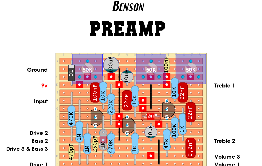
I'm about to attempt to build a Benson Preamp with veroboard using SMD J201s.

Their docs call for the builder to bias it as per PedalPCB instructions. However I notice that the veroboard was designed and uploaded months before PedalPCB released a new revision.

I guess my question is for someone who can look at the veroboard and determine whether the revision means that I'd need to bias the pedal as per the old version of PedalPCB instructions, or was the revision not to the schematic, but rather to the layout of the PCB?

Veroboard

PedalPCB new revision

Any help here will be appreciated, I'm building it for a friend and this will be my first time biasing a circuit

Thanks!
Kyle
 
As per this FSB thread that both @Robert and the designer Chris Benson both participated in:


Q1 - 5V (one poster said 5.2V gave the least clipping, but basically the original Benson pedal doesn’t have a trimpot for Q1 at all, the bias is set with a 12K resistor, so it’s likely that value was chosen to give close 5V most of the time, and that its function in the circuit isn’t so critical that it needs to be dialed in *exactly* and anything close to 5V will sound “good enough”)

Q2 - 4V

Q3 - 4V

I switched to just biasing SoBs to 5V/4V/4V instead of trying to pre-set the trimpot for 2K and they’ve sounded consistently good and consistently like the OG Benson.
 
Last edited:
i biased mine just by ear and it sounds great. if you just keep going around tweaking the trim pots you can get it sounding great even without breaking out the meter
 
As per this FSB thread that both @Robert and the designer Chris Benson both participated in:


Q1 - 5V (one poster said 5.2V gave the least clipping, but basically the original Benson pedal doesn’t have a trimpot for Q1 at all, the bias is set with a 12K resistor, so it’s likely that value was chosen to give close 5V most of the time, and that its function in the circuit isn’t so critical that it needs to be dialed in *exactly* and anything close to 5V will sound “good enough”)

Q2 - 4V

Q3 - 4V

I switched to just biasing SoBs to 5V/4V/4V instead of trying to pre-set the trimpot for 2K and they’ve sounded consistently good and consistently like the OG Benson.
Hey man, so I've reached this step. I've made Q2 and Q3 equal 4V. Question here, is something like 4.04-4.06 kind of values okay?

My main question is about Q1 though. You mentioned that biasing 5V for Q1 is preferable to setting 2K on the trimpot. I've tried both and they are very different.

What I mean is that on this 50K potentiometer, setting it to 2K is basically dialled all the way down, and gives a voltage on the drain to something like 7.7 (paraphrasing here), but if I set the drain to 5v, then the potentiometer is closer to something like 30K (just visually, by that I mean the pot is just over half way turned up) instead of 2K. I did the method of jumping the drain up to the diode and testing the resistance there (recall the discussion elsewhere about 1.67K being the target in this instance).

So my question is SHOULD I be getting 5V if the potentiometer is set to 2K resistance? Because I'm certainly not getting that at all
 
Hey man, so I've reached this step. I've made Q2 and Q3 equal 4V. Question here, is something like 4.04-4.06 kind of values okay?
Yep, that’s more than close enough
So my question is SHOULD I be getting 5V if the potentiometer is set to 2K resistance? Because I'm certainly not getting that at all
In a perfect world, yes; Q1 in the original Benson pedal was measured, and it was biased to about ~5V (I think 5.2V) with a 12K bias resistor.

But J201s have a pretty wide allowable variance on their spec sheet, hence why the PedalPCB board changed it to a 10K and a trimmer instead of just leaving it at 12K, to allow hitting the right bias (i.e. ~5V) with a wider range of J201s.
 
Back
Top