You are using an out of date browser. It may not display this or other websites correctly.
You should upgrade or use an alternative browser.
You should upgrade or use an alternative browser.
Black Cat OD-1
- Thread starter joelorigo
- Start date
Anyone ever owned one of these? Know what’s going on inside it?
It's all about the IC:
The OP275 is the first amplifier to feature the Butler Amplifier front-end. This new front-end design combines both bipolar and JFET transistors to attain amplifiers with the accuracy and low noise performance of bipolar transistors, and the speed and sound quality of JFETs. Total Harmonic Distortion plus Noise equals that of previous audio amplifiers, but at much lower supply currents. A very low l/f corner of below 6 Hz maintains a flat noise density response. Whether noise is measured at either 30 Hz or 1 kHz, it is only 6 nV/√Hz. The JFET portion of the input stage gives the OP275 its high slew rates to keep distortion low, even when large output swings are required, and the 22 V/ms slew rate of the OP275 is the fastest of any standard audio amplifier. Best of all, this low noise and high speed are accomplished using less than 5 mA of supply current, lower than any standard audio amplifier. Improved dc performance is also provided with bias and offset currents greatly reduced over purely bipolar designs. Input offset voltage is guaranteed at 1 mV and is typically less than 200mV. This allows the OP275 to be used in many dc coupled or summing applications without the need for special selections or the added noise of additional offset adjustment circuitry. The output is capable of driving 600W loads to 10 V rms while maintaining low distortion. THD + Noise at 3 V rms is a low 0.0006%.
Chuck, Please Explain!
Chuck D. Bones
Circuit Wizard
I'm not going down that rabbit hole.
I will say this: those 220pF caps from the - input of the opamps to gnd are a definite no-no, can cause oscillation.
The OP275 is a good opamp, a bit pricy. I fail to see the need for low THD in an overdrive pedal.
Other than that, nothing notable about this circuit. You can find the schematic here.
Chuck D. Bones
Circuit Wizard
You can do the same thing with a Marshall Guv'nor (Governator), just leave out the LEDs and bypass the Tone controls. Or leave them in. Socket the opamp and try different ones, even OPA2134 or OP275.
Or Build a Bluesbreaker and leave out the diodes. Etc, Etc, etc.
There is NOTHING unique about this circuit except those two caps in the wrong place.
Or Build a Bluesbreaker and leave out the diodes. Etc, Etc, etc.
There is NOTHING unique about this circuit except those two caps in the wrong place.
jesuscrisp
Well-known member
I built one ages ago, than fewer ages ago I tried improving it. Some facts and thoughts:
- The 100n caps are most likely wrong, at least for the input cap. If you use 100n caps in all spots, you'll get a very dark/muddy/boomy/younameit pedal. My first build had 47n caps instead, but today I'd do a smaller input cap (10-22n), 100n caps between the stages and a 1 uF output cap for example.
- Despite what Mr. Chuck says, the 220pF caps don't cause oscillation (in this circuit). Leaving them out I imagine you'll get less smoothing, but that could be probably countered by just adding a smoothing cap in the first gain stage feedback loop and/or increasing the value of the 100pF one in the second stage.
- Also going against Chuck yet again, this really isn't a BB/Guvnor style circuit, as the first gain stage is an inverting one and the gain control is closer to a Big Muff one rather than what you'd find in a BB/Guvnor, plus it misses any sort of tonestack.
- The OP275 is actually quite unique sounding in drive circuits, but often in a weird or downright unpleasant way. in this one it's slightly starved by the 430R resistor off the power supply, which makes it clip earlier and fuzzier too. You can try different op amps, but since this is sort of an op amp fuzz, the OP275 with it's weird and fuzzy breakup in my opinion is rather essential.
- Here I'd like to note that the schematic linked above has a 430R resistor to create the Vcc seperately from the power filter cap and Vref voltage divider. Not sure if that is correct or not, but it creates more noise and an asymmetrical Vref. While noise is generally not good, you can achieve and asymmetrical Vref by just using 2 slightly different resistors instead, or even make it a trimmer or pot like the Tech21 XXL does ("warp control").
- I have experimented with diodes, both soft and hard clipping and tonestacks and I feel like it's worth adding them on a switch, helps a bit with the otherwise fizzy note decay of the op amp distortion.
Chuck D. Bones
Circuit Wizard
Putting those 220pF caps there degrades the phase margin substantially. The circuit could be right on the edge of oscillation or oscillating at RF frequencies. Have you checked for ringing or oscillation with a scope? In any case, those caps do not provide filtering because of where they are located in the feedback loop.
- Despite what Mr. Chuck says, the 220pF caps don't cause oscillation (in this circuit).
- Also going against Chuck yet again, this really isn't a BB/Guvnor style circuit, as the first gain stage is an inverting one and the gain control is closer to a Big Muff one rather than what you'd find in a BB/Guvnor, plus it misses any sort of tonestack.
True. That inverting input presents a fairly low impedance to the guitar and will interact with the guitar's controls and pickups. The Marshall gain control is different, it throttle both stages simultaneously. Tone stacks are easily bypassed or altered.
- The OP275 is actually quite unique sounding in drive circuits, but often in a weird or downright unpleasant way. in this one it's slightly starved by the 430R resistor off the power supply, which makes it clip earlier and fuzzier too. You can try different op amps, but since this is sort of an op amp fuzz, the OP275 with it's weird and fuzzy breakup in my opinion is rather essential.
That 430Ω resistor in series with the power supply is something else that is bad practice with opamps. If their power supply rails are not bypassed, opamps can behave erratically and the mfgr would say "don't do that." Pedal builders do some crazy shit and to quote my mentor Arpad: "If it's doable, somebody vill do eet." It was a sarcastic statement meaning that just because you can to something, that doesn't make it a good idea.
- Here I'd like to note that the schematic linked above has a 430R resistor to create the Vcc seperately from the power filter cap and Vref voltage divider. Not sure if that is correct or not, but it creates more noise and an asymmetrical Vref. While noise is generally not good, you can achieve and asymmetrical Vref by just using 2 slightly different resistors instead...
How did you build yours? Where was the 430Ω resistor w.r.t. the Vref divider? I DL'ed the sch from Das Musikding and it matches the one linked above. Most opamps, the OP275 included, have an asymmetrical output swing. The implication is that centering Vref between the rails does not ensure symmetry.
Can we see your schematic?
Good discussion!
jesuscrisp
Well-known member
Unfortunately I have taken it apart since, but I want to build another one sometime.Can we see your schematic?
IIRC it was basically the schematic above, but I added the AMZ SWTC3 tonestack, and a hard clipping switch for LEDs, silicon diodes or diode lift, made all film caps 47n. Not sure anymore how and where I put the 430R resistor. Things I wrote above are among others just things I know better today than back then!
Later I experimented with soft clipping in the second gain stage and added a JFET buffer after the tone control and before the volume like in a Rat, made the current limiting resistor (430R) way smaller and put it in the "right place". I remember that version lost some of the original's character though. There's only so much you can do to a circuit before it becomes something else after all, especially simple ones like the OD-1.
Chuck D. Bones
Circuit Wizard
BTW, I ran an LTSpice sim with the 220pF caps in place and it rings like crazy. The OP275 model came from ADI and must be highly accurate because it runs as slow as molasses.
jesuscrisp
Well-known member
Oh definitely!Interesting discussion here. ma I’ll keep an eye out for one on reverb. If I did happen to pick one up would anyone be interested in seeing exactly what’s inside?
joelorigo
Well-known member
I got one.The demo above is spot on. Thickens and fuzzes up the sound. I like it!


Attachments


Elijah-Baley
Active member
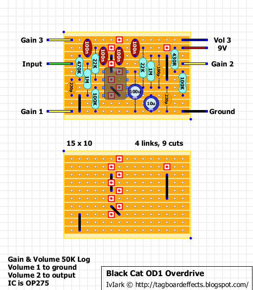
Comparing the layout above here we have: all the 100nF are, instead, 47nF.
Ceramic caps should be ok.
Electrolytics are: 100uF, correct, while the 10uF is here a 47uF.
I think the Drive pot is the B50k, and the Volume pot is log.
I see a diode... a 1N4001 between 9v and ground? It's mentioned in the schematic linked some post above, but it's not present in the draw.
I didn't check the resistor, but the picture are good, we need a few of minutes to find the value.
MichaelW
Well-known member
Oooooo, I like that guitar!
jesuscrisp
Well-known member
Awesome!
Yes, 50K log pot probably makes for a much better volume taper (that thing is loud AF!), and the 47nF are indeed the correct value it seems, 100nF just make it way too dark and boomy.
There seems to be 2 more resistors than in the schematic and layout!
Yes, 50K log pot probably makes for a much better volume taper (that thing is loud AF!), and the 47nF are indeed the correct value it seems, 100nF just make it way too dark and boomy.
There seems to be 2 more resistors than in the schematic and layout!
Similar threads
- Replies
- 14
- Views
- 1K