bread boarding Silismile fuzz face question

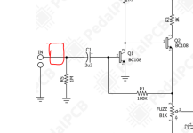
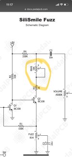
I am starting to bread board now and thought the fuzz face was a good place to start. The silismile looks interesting and close to the original:

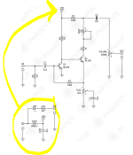
Question, the separate lower power section in the schematic, if I am not using a stomp or LED in my model, can this be omitted? Is D100 and c100 required?

Thanks, I am just trying to get the picture straight in my head.

Pb
 

Attachments

  • ff.png
    ff.png
    144.3 KB · Views: 15
D100 provides reverse polarity protection, in case you inadvertently reverse 9V and ground, with the 47u cap there to filter said power. The LED’s useful to confirm that the board is getting power. But you could connect directly if you wish.
 
That section is the power section. D100 is for polarity protection. If you're confident on powering up the breadboard you can omit this. C100 is a power filter to give you cleaner DC input. It's always good practice to put this in, but not necessary to make a functional circuit. You can simply throw this directly in the power rails on the breadboard and forget about it.
 
D100 provides reverse polarity protection, in case you inadvertently reverse 9V and ground, with the 47u cap there to filter said power. The LED’s useful to confirm that the board is getting power. But you could connect directly if you wish.
Maybe the diode and 47u cap makes sense for the breadboard. I will try connecting directly.
thanks
Pb
 
That section is the power section. D100 is for polarity protection. If you're confident on powering up the breadboard you can omit this. C100 is a power filter to give you cleaner DC input. It's always good practice to put this in, but not necessary to make a functional circuit. You can simply throw this directly in the power rails on the breadboard and forget about it.
Thanks. the diode and 47u make sense. I will add them. I was wondering if I could just put this on the power rails. Thanks for confirming. Maybe I will keep it as is and just move to the power rails.

Pb
 
That section is the power section. D100 is for polarity protection. If you're confident on powering up the breadboard you can omit this. C100 is a power filter to give you cleaner DC input. It's always good practice to put this in, but not necessary to make a functional circuit. You can simply throw this directly in the power rails on the breadboard and forget about it.
Hmm, looked at the schematic again. C100 makes sense on the power rail, as you said. D100 is not clear where to add it. I might as well put in the diode in case I snap the batter on wrong. would it go in the "IN" section?
 

Attachments

  • diode.PNG
    diode.PNG
    48.2 KB · Views: 4
Hmm, looked at the schematic again. C100 makes sense on the power rail, as you said. D100 is not clear where to add it. I might as well put in the diode in case I snap the batter on wrong. would it go in the "IN" section?
Nope. Plug your power input into the diode and then the diode into the power rails. If polarity is incorrect then nothing will reach the rails. C100 goes directly in the power rails.
 
How do you determine the value for the power filtering cap? I see 47u used a lot, is that a standard value for all 9v DC circuits?
 
Nope. Plug your power input into the diode and then the diode into the power rails. If polarity is incorrect then nothing will reach the rails. C100 goes directly in the power rails.
Great. Thanks for clearing that up!

Pb
 
Ok so it has to contracted back to the same as pin 3?

Thanks
Pb
Exactly. If you're using a wired pot for this, you can bridge pins 2 and 3 on the pot itself, or better still IMO solder all three leads to the pot for later re-use. Then connect pins 2 and 3 to the same column on the breadboard. If using a trimmer, make a small u-shaped bridge from solid wire (offset from a resistor or diode lead) and connect trimmer pins 2 and 3 accordingly.
 
Exactly. If you're using a wired pot for this, you can bridge pins 2 and 3 on the pot itself, or better still IMO solder all three leads to the pot for later re-use. Then connect pins 2 and 3 to the same column on the breadboard. If using a trimmer, make a small u-shaped bridge from solid wire (offset from a resistor or diode lead) and connect trimmer pins 2 and 3 accordingly.
Thanks for the detailed explanation! That makes perfect sense

Pb
 
breadboard_02.jpg

Since a picture is worth many thousand of my words, there are numerous options when it comes to breadboard-friendly pots. I use these male-to-male leads (far right), cut them in half, strip them, and solder them to the lugs. The heat shrink cable helps them not to become dislodged too soon since they are quite flimsy. Or you can use a trimmer (middle right) which sits nice and flush on the breadboard but is a bit finicky to adjust. Finally, a PCB mount pot (middle left) will fit tidily if you're not inclined to fiddle with leads. Just press it down gently and it'll snap into place.

breadboard_01.jpg

The selfsame male-to-male leads together with crocodile clips are handy for off-board wiring, as you see. Avoid the transparent breadboards if you can; they are much more prone to miswiring, at least with my eyesight (which ain't what it was). While you're at it have a look at the forum breadboarding resources. Plenty of good stuff there.

Since I live at the bottom end of Africa, there's usually a fairly long wait for 'proper' PCBs to arrive. I keep myself amused while waiting by breadboarding, which makes mods and substitutions really easy. Best of luck with your enterprise. Let us know how it goes if you like.
 
View attachment 66122

Since a picture is worth many thousand of my words, there are numerous options when it comes to breadboard-friendly pots. I use these male-to-male leads (far right), cut them in half, strip them, and solder them to the lugs. The heat shrink cable helps them not to become dislodged too soon since they are quite flimsy. Or you can use a trimmer (middle right) which sits nice and flush on the breadboard but is a bit finicky to adjust. Finally, a PCB mount pot (middle left) will fit tidily if you're not inclined to fiddle with leads. Just press it down gently and it'll snap into place.

View attachment 66121

The selfsame male-to-male leads together with crocodile clips are handy for off-board wiring, as you see. Avoid the transparent breadboards if you can; they are much more prone to miswiring, at least with my eyesight (which ain't what it was). While you're at it have a look at the forum breadboarding resources. Plenty of good stuff there.

Since I live at the bottom end of Africa, there's usually a fairly long wait for 'proper' PCBs to arrive. I keep myself amused while waiting by breadboarding, which makes mods and substitutions really easy. Best of luck with your enterprise. Let us know how it goes if you like.
great pics! I have to order a few larger bread boards and parts to make a proper prototyping station that I can pick up and walk over to the amp to test. Right now it is very delicate. I guess that is the balance between real pcb and proto board. Pedalpcb and tayda take 2-3 weeks for me in Canada. It is probably faster in the states.

Pb
 
Tayda's quite quick here (3-4 days usually) but one waits a long time for boards (6-8 weeks, depending on customs clearance). I have one of these, which is a bit more robust: https://www.pedalpcb.com/product/protoboard-micro/

Just waiting for the terminal blocks to make it into a permanent breadboard test bed. Depending on how far you want to go with breadboarding, you might find it useful, and @Robert has some even more deluxe super-duper options if you're so inclined.
wow, 3-4 is fast. I have to use the cheap thailand shipping so I don't get screwed by customs. I will order one of those protoboards. I was waiting for them to update the build instructions, but it should be fairly straight forward.

thanks
Pb
 
Let me know when it reaches you and I’ll help you get the right parts. I need to build mine soonish but waiting to place a Tayda order.

And BTW I (ahem) I pay a small fortune in shipping costs because we don’t have a cheap option available. Doesn’t seem the slightest deterrent, though 😉

Customs duty is also pretty hit or miss. Same applies. Later, all best.
 
Back
Top