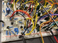
DEMO Breadboard builds [Boss MT-2 Metal Zone Bonanza + mods //// Eight Ball Overdrive (Marshall JCM800 Pedal) /// Mofeta (EAE Model feT)]

This post contains an audio or video demo

owlexifry

Well-known member
i should have started breadboarding a long time ago.
IMG_7418.jpeg
it all started about 6 months ago when i wanted to start testing out some MP38 Ge transistors in basic circuits with a cheap 400 point breadboard and the brilliantly convenient ProtoBoard Micro.

then i finally 'got it' and realized why breadboarding even exists. (holy shit - i can just bang out a circuit real quick with no soldering bullshit, make super fast mods and then reuse all the parts for something else later)
I knew the time was coming that I'd have to sort out something bigger.

This became especially urgent as my Mofeta board hit the top of my que.
I'd already drilled the enclosure for it, and then my problem was - I've been pondering for some time as to how I really want to build it - e.g. Model feT vs Citadel - after referring to @TucsonSean 's excellent thread about building a Super Lead/1987 inspired circuit on the Mofeta board. (since the Model T and Super Lead/1987 circuit topologies are largely identical).
I also have a Golden Falk board, so I was wondering if I should even bother with a Super Lead type circuit. I almost posted one of those threads looking for opinions, and while I was typing it out I realized what I needed to do - just get on with it, and breadboard the Mofeta and then compare both.
Ordered some busboards from mouser and they landed last week.
As fantastic as the full size Protoboard looks, well, I needed a solution immediately.

- Basically, I just went with Chuck Bones baking tray idea, so I went to a thrift shop and grabbed one for $3.
IMG_7388.jpeg
- Fortunately I had some leftover 2"/2" angle/L-shape aluminium sitting in the shed.
- Cut two identical lengths of aluminium.
- clamped them together to form a U shape, drilled, and bolted them together, and bolted that U-piece to the baking tray.
- to ensure shielding effect, all mating surfaces between the x2 pieces of aluminium, and the baking tray were filed and sanded before fastening, for maximum continuity.
- measured, marked and drilled positions for jacks, pots, bypass switch and an outie DC jack.
- sanded the 'faceplate' surface down a few a grits (40 to 400) for a pleasant finish.

result:

then it was time to measure some MMBF5457 JFETs for the Mofeta/EAE Model T circuit build.
IMG_7401.jpeg

- soldered I/O wiring and grounds.
(input jack sleeve is star ground, I/O tip/signals coming off DPDT switch, power lead directly off DC jack)
IMG_7402.jpeg

to my great surprise:
- it actually worked the first try (with couple minor errors)
- sweet fuck all noise from this build. with both brite and normal gain turned up to 3pm or more, absolutely acceptable idle noise levels, very minimal. so stoked.
- had concerns about the non-stick coating interfering with the ground plane-shielding effect of the pan, but it appears to be fine with it intact. Still not really sure whether it makes a difference or not, but this build appears remarkably quiet considering how noisy some fuzz/distortion builds have been on my 400 point/ProtoBoard Micro.

IMG_7416.jpeg

fresh out the oven, sitting outside to cool after correcting errors
IMG_7492.jpeg

DEMO
 
update:
i’ve now had some time to mod the mofeta for super lead-inspired tones (and record a demo with an SM57 this time)

this is where ive ended up:
IMG_7573.jpeg
- after cutting so much low end with a 2n2 on the bright channel, i felt that changing all the back end 100n caps to 22n was taking all the life and thickness out of it, so ive left those as is, cos it sounds better.
- a 470p bright cap on the bright/lead channel is nice to have, but definitely gotta have it on a switch i reckon.

- the tones from this circuit represent a shitload more overdrive than i would expect from a real super lead/plexi.

so while recording the demo for these mods, i went ahead and tried out 12V supply instead of the usual 9V.
well, holy crap - it was a surprisingly noticeable difference.
bigger sound, more low end/thickness, punchier, more articulate, just better.

DEMO (w/ 12V supply):
 
Last edited:
Awesome! I wish there were more build reports like this one (of people's BB'ing rig).

Hey! That doctored-schematic sure looks familiar! 😸


I suggest you get some of the female to male jumper wires, the female ends slip right onto the pot legs, no soldering required:

e79d3e2f-4ff3-435e-8975-d6a702e6f3cf-jpeg.24307
 
Awesome! I wish there were more build reports like this one (of people's BB'ing rig).
ay cheers! i was just stoked on the results of this super budget rig and thought i’d share the results.
Hey! That doctored-schematic sure looks familiar!
haha just being 100% transparent with the sources for my ideas 😉

I suggest you get some of the female to male jumper wires, the female ends slip right onto the pot legs, no soldering required:

e79d3e2f-4ff3-435e-8975-d6a702e6f3cf-jpeg.24307
yeah these look great. wtf do they come like that with the spade connectors attached?

Sounds like that circuit deserves a proper build🤘
hell yeah, i reckon this is what i’ll be doing with the mofeta board. probably the best JFET distortion ive tried so far.
 
haha just being 100% transparent with the sources for my ideas 😉


...


...I just showed somebody else's mods on the schematic that I didn't draw — I didn't do any of the work.
Glad somebody's getting some use out of the notated schem!


yeah these look great. wtf do they come like that with the spade connectors attached?


Yes, attached.

TAYDA has the jumper-wires in different lengths and configurations. I recommend getting a few of each type, because I've always found that I think I only need one type/length and then wind up needing other types/lengths ie thought I only needed long female/male, but could use some shorter ones and short male/male ( for multiple breadboards while breadboarding large circuits, for example). Tayda's not the only source, of course.

Sizes: 100mm 200mm 300mm
Type: female/male, female/female, male/male, and male/female ;)


a-2379.jpg


Just peel off however many you need, singles or three-at-a-time for pots...etc.
 
How do you think this compares to the golden Falk.
i’d have to build the golden falk and get back to you. i’ve got the board, so it’ll happen sooner or later 😅

TAYDA has the jumper-wires in different lengths and configurations. I recommend getting a few of each type, because I've always found that I think I only need one type/length and then wind up needing other types/lengths ie thought I only needed long female/male, but could use some shorter ones and short male/male ( for multiple breadboards while breadboarding large circuits, for example). Tayda's not the only source, of course.

Sizes: 100mm 200mm 300mm
Type: female/male, female/female, male/male, and male/female ;)


a-2379.jpg


Just peel off however many you need, singles or three-at-a-time for pots...etc.
crikey, these look perfect. thanks for the tip.
 
since I felt this circuit was worth highlighting, i decided it was most relevant to post about it on this thread.

firstly, many thanks to @Robert for making the schematic available so soon 🙏

initial speculations on the circuit/build discussed here:

IMG_8838.jpeg

since then, I've got a J201 for the input buffer now (subbed for 2SK209) - which made no perceptible difference to a 2N5089, cbf trying different opamps, so still got a TI RC4558 in IC1 (clipping stages), and an LF353 for IC2 (output buffer and VREF voltage follower)

why LF353?
1749275331217.png

Unfortunately I don't have an A25K, so I used a B25K, and tried to factor that in when adjusting the gain control.
IMG_8844.jpeg
had the opportunity this afternoon to properly try it out, and heck this is fun to play.
it really does capture that classic Marshall rock sound.
perhaps a little more gain/drive available than a real JCM800 (as these things often do) but that's not a bad thing.
cleans up real nice with the guitar volume control, crunchy tones for days, but isn't harsh at all.


only downside for me, is it doesn't really do metal. doesn't sound good boosted with a drive at all. but that's ok, this pedal/circuit isn't really for that.
but it does absolutely rock a convincing JCM800 sound, and if that's your thing, I do recommend building one:
⬇️
 
Last edited:
i was considering posting this in the modifications sub-section but im not sure that a couple cap changes is worth a post there.
or anywhere really, but i guess this thread will do since the MT-2 is the largest circuit i’ve breadboarded so far.

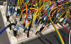
IMG_0889.jpeg

after fixing a few errors, the build sounded pretty much identical to a genuine unit.
even with the output buffer skipped and output level pot changed from 50KB to 100KB as per GCI’s MT-2 schematic.
(i mostly followed the original boss schematic, but took the cues on skipping the switching stuff etc. from the GCI schematic)

as was seen on the workbench thread, here’s an inadvertent demonstration of an opamp clipping mod:

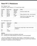
so then i had a little search around for MT-2 mods and found these:
IMG_0843.jpeg
the 'dieznerr' mod thing was kinda crap.
just made everything sound flat.

didn’t bother with the other one.

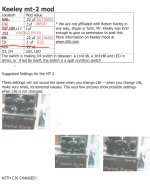
IMG_1180.jpeg
for some reason a lot of these keeley ‘mod’ values weren’t any different from the boss schematic. i counted a total of x3 cap value changes.
- input cap/C42 mod didn’t seem to do a lot, but i left it at 100nF anyway.
- the post-clipping/distortion gyrator/C17 mod cuts a bit of the harsh high end. works for me. makes it easier to use a little more treble/high mid.
- the ‘EQ’/C9 mod i didn’t like, it seemed to just limit the EQ and make it worse.
- the LED clipping mods made it sound unwieldy and limited the EQ, i preferred the grind of the stock/4148 pair.

so here’s how it sounds with the C42 mod and the C17 mod.
(and yes boosting the MT-2 with an SD-1 works really well)

drop C
drop G#

then i had an idea.
there was a decent amount of space left on the breadboard and so i thought,

what if i put the MT-2 EQ after a different distortion circuit?

how about a RAT? that’ll be quick.

so i pulled out an LM308HZ and plonked in a rat circuit minus the filter etc. and route it straight from the diodes into the MT-2 EQ (via 10uF coupling cap in between)
IMG_1127.jpeg
still sounds a lot like a rat.
worked well. EQ does the thing.

then i did the same thing with a big muff V2
[Q3 collector -> 10uF -> MT-2 EQ (at R28)]
just grabbed x3 2N3904 and went with a 1973 #4 schematic that i already had downloaded on a tablet.
IMG_1150.jpeg
result?
very much retained a strong big muff character.
for me, this experiment kinda flattened the whole ‘big muff sound is all in the tone circuit’ argument that i’ve seen around 😏
no matter what i did, that big burly fat muff distortion fuzz is all there, inescapable, and sorta kinda limits what the MT-2 EQ can really offer, but regardless this was surprusingly good and made for an interesting muff.

unfortunately i had the bass control up way higher than i’d like it to be for the demo (got lost in the bass, my bad)
^this also highlights why the the treble, bass, and middle pots all need to be W taper.
i used B taper and it makes fine control at the higher / lower extremes a lot more sensitive/difficult to dial in.
 
Pro level breadboarding. I like the sounds you're getting, with and without mods. I've had basically the opposite idea about the tone stack - take only the distortion stages of the Metal Zone and put the Marshall Valvestate or Ampeg VH-140C tone stack after it. Could make for a decent 90s death metal preamp in a box type of thing I think, although I guess even the stock Metal Zone already kind of is just that.
 
Pro level breadboarding. I like the sounds you're getting, with and without mods. I've had basically the opposite idea about the tone stack - take only the distortion stages of the Metal Zone and put the Marshall Valvestate or Ampeg VH-140C tone stack after it. Could make for a decent 90s death metal preamp in a box type of thing I think, although I guess even the stock Metal Zone already kind of is just that.

THIS. The frequency response of the Metal Zone is extremely similar to that of the VH140. I've been procrastinating on adjusting the VH140 to exact Metal Zone frequency specs and adding the tone stack from the GK 250ML after it for a good three years now (I'll get to it, I swear!), but it's heaps fun to play "mix and pair" with circuit snippets, particularly with high gain pedals. Infinite combinations of fun.
By the way, the distortion circuit of the Valvestate sounds nothing like a Valvestate if you remove the Contour - it becomes just another average High-ish gain device, a bit dull and honky...
Has anybody done a Russian Muff with HM-2 tonestack yet? 😜
 
Back
Top