Bring out yer Diptrace

I mean mechanical components all on the same board.

I understand the allure but it’s a gamble tje more components you board mount.
The one concession I'm making in terms of reliability is the 3pdt switch. I sourced good quality switches for this, but in the future I'd like to forego it and work in a relay bypass. With the 3pdt a bad switch could nerf the whole board, but this is a prototype so I'm ok using it.

I've used the cheaper Chinese ones in all my pedals up until now and I've only had 3 (out of at least 100) go bad, but still I didn't want to permanent mount one of those into the board.

In the next round I'm probably going to use TS neutrik jacks which don't have the pads for the ring terminal, which allow better trace routing underneath them. When I get to building this board up I'm going to check out how much vertical space there is between the pots and the jacks and see if I can squeeze them together better to make more room for relay bypass components.

I'm also going to see if there is room to put anything on the bottom of the board. I have a trim pot for the LED brightness there now as an experiment. If it doesn't fit I can install a jumper instead, but I'd like to be able to squeeze the relay itself on the bottom side between the audio jacks. Fingers crossed.
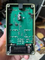
 
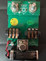
This is my inspo
IMG_7467.JPG

They used a daughterboard for the pots whereas I used long leg pots. In the MXR pedals I've taken apart, the side jacks' holes have been extended down to the base of the enclosure, making the hole into a tombstone shape so the pedal can be assembled with the nuts attached to the jacks. Seeing this gives me confidence about my design as it's meant to be assembled the same way.
IMG_7468.JPG
 
Here's a quick follow up

My board showed up today and I put it together, and learned a few things.

1- the patterns and measurements aren't exactly correct, despite my best efforts. My tone knob ended up a bit further down than I planned on and it interfered with the audio jacks. I got it to work but it wasn't as easy as I was trying to plan for.

2- I should have looked out for my future self and drawn on alignment lines so I can set the board on top of the enclosure and quickly get references for where to drill for the jack, led bezel, and switch (and probably the pots as well)

3- my holes for the side jacks ended up in the correct spot but I had to concentrate to get them there. I had to concentrate on pretty much everything. The idea behind this exercise is to eliminate concentration and just be able to assemble a board while turning off my brain

4- the neutrik side jacks squeeze into a normal 1590b. They are a good fit in the ones from stompboxparts that are slightly oversized.

5- the footswitch I ordered from stompboxparts didn't fit the layout exactly so I should have checked the hole spacing instead of assuming they were all the same. I trimmed the legs to make it fit

Hell yeah
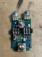
IMG_7487.jpg

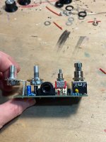
I forgot about the height of the switch body. Also see how the legs for the pots are at an angle - when I designed it I meant for them to be straight.
IMG_7489.jpg

I forgot to include an enclosure ground so I grounded the tone control's pin 1 to the pot body. Then the pot body contacted the input jack leads and I had to do some troubleshooting bc it grounded the input signal.
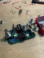
IMG_7490.jpg

The height of the long leg pots put the side jacks exactly where I wanted them to be, and the footswitch was in a good position as well. I wish the jacks weren't so big, they take up a lot of room.

I think for the next one I'll include board cut outs (or enlarge the holes) in the center of each component and use them as guides for a center punch so I can place the board directly on top of the enclosure and not make any measurements on the face of the pedal at all. I think what threw me on this one is I derived my measurements from an older pedal while nowadays I space my knobs out a bit further to make room for labels.
 
Last edited:
I don't recall where, maybe tayda, but there are long legged switches that may be of use.
Another alternative is use a long bat switch and an oval hole. Downside is the only thing mechanically holding the switch is the solder. If I were to go that route with your current setup I would standardize use of DPDT or 3PDT in that spot. That would give much more mechanical strength.
I believe there are also tall shoulder/collar switches available but they don't come in short bat iirc.
End/ My twenty percent of a dime no one asked for.
 
I don't recall where, maybe tayda, but there are long legged switches that may be of use.
Another alternative is use a long bat switch and an oval hole. Downside is the only thing mechanically holding the switch is the solder. If I were to go that route with your current setup I would standardize use of DPDT or 3PDT in that spot. That would give much more mechanical strength.
I believe there are also tall shoulder/collar switches available but they don't come in short bat iirc.
End/ My twenty percent of a dime no one asked for.
I like the elongated hole but I can't reliably drill them. I'll look around for a long leg switch. I know the solder type switches pins are longer, and I wonder if they may work with pin headers.
 
Man if I had a dollar for every time I've said that, I would have many many dollars.

Looks great though my dude, all things considered I would call this a win.

+1 on both points.

You're basically paying the "tuition" cost. A couple minor refinements and your next build should indeed be possible without thinking, and then you have a nice template you can just recycle for future designs.
 
Back
Top