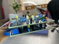
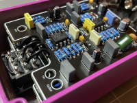
This is what I get for not making sure there are build instructions before buying all the parts etc.
I am in the process of building two of these, one for a friend, one for me. I populated the boards at the same time, but am assembling them one at a time. I totally suck at visualizing in advance how things fit together, and that's why I rely on build instructions.
If there are two ways to put something together, I will choose the wrong one every time.
In this case, when I got the first one all together and ready to go into the enclosure, I noticed something was VERY wrong. First, I soldered the short pins into the top (looking down from the bottom of the case) of the bottom board, and then soldered the long pins to the switch, so that the switch board was ON TOP of the main board.
When I went to install the two boards into the enclosure, and pushed all the controls and switch into the enclosure, the boards sat at an angle with the front of the boards (nearest the jacks) up higher than the bottom of the boards. (That meant the bottom wouldn't close correctly and if I tried, would have damaged some components.)
It took a while for me to realize that if I had mounted the switch to the BOTTOM of the board, then it would have assembled evenly.
Now that I have, through trial and error (or error and more error as I usually call it) figured it out, I wonder how other people know how to properly position the switch and header pins.
I looked for "gut shot" pictures and managed to find one, which looked to me that they had indeed positioned the long pins facing downwards (or towards the top of the enclosure, depending on your pt. of view) with the switch circuit board UNDERNEATH the top board. That seemed to confirm I had now mounted the switch correctly, and sure enough, when I plugged on board into the other and all the controls and the switch were pushed through their respective holes, now the boards were positioned flat and the bottom cover fit perfectly. Whew!
It wasn't much fun trying to desolder the header pins but I managed to do so without ruining either the daughter or main boards. Let's hear it for solder wick and a vacuum solder sucker. The header was a total loss, but I have lots of headers.
So the correct way to attach the switch daughter board is to position the plastic portion of the 6 pin header BELOW the main board so that the short pins push UP into the main board, and the long pins face downward and go downwards through the switch daughter board which is now positioned underneath the circuit board.
I hope this post helps someone else avoid making the same mistake.


