Byzantium Flanger - How To Correctly Attach The Stomp Switch (A Build Guide Would Have Helped Immensely)

BQFS

Member
This is what I get for not making sure there are build instructions before buying all the parts etc.

I am in the process of building two of these, one for a friend, one for me. I populated the boards at the same time, but am assembling them one at a time. I totally suck at visualizing in advance how things fit together, and that's why I rely on build instructions.

If there are two ways to put something together, I will choose the wrong one every time.

In this case, when I got the first one all together and ready to go into the enclosure, I noticed something was VERY wrong. First, I soldered the short pins into the top (looking down from the bottom of the case) of the bottom board, and then soldered the long pins to the switch, so that the switch board was ON TOP of the main board.

When I went to install the two boards into the enclosure, and pushed all the controls and switch into the enclosure, the boards sat at an angle with the front of the boards (nearest the jacks) up higher than the bottom of the boards. (That meant the bottom wouldn't close correctly and if I tried, would have damaged some components.)

It took a while for me to realize that if I had mounted the switch to the BOTTOM of the board, then it would have assembled evenly.

Now that I have, through trial and error (or error and more error as I usually call it) figured it out, I wonder how other people know how to properly position the switch and header pins.

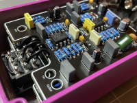
I looked for "gut shot" pictures and managed to find one, which looked to me that they had indeed positioned the long pins facing downwards (or towards the top of the enclosure, depending on your pt. of view) with the switch circuit board UNDERNEATH the top board. That seemed to confirm I had now mounted the switch correctly, and sure enough, when I plugged on board into the other and all the controls and the switch were pushed through their respective holes, now the boards were positioned flat and the bottom cover fit perfectly. Whew!

It wasn't much fun trying to desolder the header pins but I managed to do so without ruining either the daughter or main boards. Let's hear it for solder wick and a vacuum solder sucker. The header was a total loss, but I have lots of headers.

So the correct way to attach the switch daughter board is to position the plastic portion of the 6 pin header BELOW the main board so that the short pins push UP into the main board, and the long pins face downward and go downwards through the switch daughter board which is now positioned underneath the circuit board.

I hope this post helps someone else avoid making the same mistake.
 
the key to all of this is to DRY FIT everything (and i mean everything) to ensure fitments etc. before applying solder to anything.

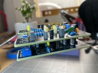
(here's a pic where i've checked the fitment of the two boards together with the header pins/sockets already mated together, which is how they should be when you go to solder them together - after checking fitment inside the enclosure with the pots etc.)
IMG_2480.jpeg

am i gigantic dumbass and fuck shit up constantly - so if i can do it, you can too 💪

So the correct way to attach the switch daughter board is to position the plastic portion of the 6 pin header BELOW the main board so that the short pins push UP into the main board, and the long pins face downward and go downwards through the switch daughter board which is now positioned underneath the circuit board.
idk, but you also have the option to just not use the switch daughter board, makes this lot easier:
1763600086037.png
(3PDT daughterboards are just a nuisance IMO)
 
Last edited:
Here's mine

GotwcA3.jpeg


lZqsrCk.jpeg


Pin headers I used (they are low profile which is why my bottom board looks weird, though in the end mounting the components to the other side of the board was unnecessary)
D31rbZj.jpeg


Single ground wire
CWru5LE.jpeg


zbO0nHc.jpeg


Make sure to get the low profile elec caps

Also small bear has some as well
 
I think you are asking what type of rigid pin headers people use to attach the switch daughter board to the main board?

The relationship of the switch to the bottom board in terms of height cannot be standardized - this is because there are different types of pin headers which have differing heights and there are different switches which are also different heights, and can be adjusted. So your project will likely end up different from other peoples due to the plethora of different spec parts available.

As a general rule you want the individual pieces to be able to move around slightly, as securing them in different places that don't allow for the same type of movement will put uneven stress on the board and lead to failure. That's why I used wires to connect my switch as they'll prevent the stresses endured by the footswitch from transferring to the board.

A huge bonus is I didn't have to worry about locating the footswitch to the main board in its up/down dimension as well.

Once you have some more builds down it becomes easier to spot patterns and visualize what the final product will look like. This was one of my first dual layer projects and it shows. But just be patient and you'll work it out.
 
the key to all of this is to DRY FIT everything (and i mean everything) to ensure fitments etc. before applying solder to anything.

(here's a pic where i've checked the fitment of the two boards together with the header pins/sockets already mated together, which is how they should be when you go to solder them together - after checking fitment inside the enclosure with the pots etc.)
View attachment 106481

am i gigantic dumbass and fuck shit up constantly - so if i can do it, you can too 💪


idk, but you also have the option to just not use the switch daughter board, makes this lot easier:
View attachment 106482
(3PDT daughterboards are just a nuisance IMO)
Thanks for your detailed response. This is about the 12th pedal I've built, not counting the dozen I have built for resale, but it is definitely the first two-layer pedal. I definitely fit the two boards together to make sure the fit was perfect. A dry fit is the ONLY fit in this case, because the two boards do not solder to each other.

Yes, in retrospect it would have been better (at least for me) had I used six wires instead of the 6 pin double male header but things are always more clear to me after the fact. I personally just think it looks better to use the daughter board and header, although it certain requires more trial and error to adjust the nut for the stomp switch on the inside of the enclosure to eliminate stress on the main board.
 
I think you are asking what type of rigid pin headers people use to attach the switch daughter board to the main board?

The relationship of the switch to the bottom board in terms of height cannot be standardized - this is because there are different types of pin headers which have differing heights and there are different switches which are also different heights, and can be adjusted. So your project will likely end up different from other peoples due to the plethora of different spec parts available.

As a general rule you want the individual pieces to be able to move around slightly, as securing them in different places that don't allow for the same type of movement will put uneven stress on the board and lead to failure. That's why I used wires to connect my switch as they'll prevent the stresses endured by the footswitch from transferring to the board.

A huge bonus is I didn't have to worry about locating the footswitch to the main board in its up/down dimension as well.

Once you have some more builds down it becomes easier to spot patterns and visualize what the final product will look like. This was one of my first dual layer projects and it shows. But just be patient and you'll work it out.
As I mentioned previously, this is about the 12th pedal I have made, not counting the ones I made for resale. No matter how many I do, I still end up making errors like this one because I just cannot visualize things correctly. All I would have needed to get this right the first time was some sort of build guide which would have mentioned either to use individual wires to connect the switch to the board or to make sure the switch mounted UNDER the board and not on top of it. Not everyone, regardless of experience, can figure out these kinds of things in advance.

I have a few more pedals I will build, mostly for resale, but none of them use stacked boards. But if, someday, I do another similar one, at least I will know what to watch out for.

Thanks very much for your considered response.
 
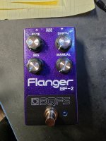
It's the purple sparkly powder coat. I use these for my commercial pedals. Before I got fed up with drilling the holes and never getting them quite right (and ruining enclosures in the process) I used to just buy them from Tayda. Now I buy them from Amplifyfun in Portland. He may buy them from Tayda too - I don't care. Spencer does fine work, well worth the price. I have him drill the holes and apply the graphics. The graphics for my commercial pedal (2-band 70s pre-EB Stingray preamp) were done by a friend of mine. The graphics design for this one was done by a Reddit buddy of mine in the UK and improved upon (adding the white lettering) by Spencer.

The BQFS stands for my company, Bud's Quality Fun Stuff.

I have no intention of selling these commercially as I am too afraid Boss may come after me. I'm just building one for my best friend and one for myself.

Now, if I could just get the damned thing to work. First I attached the switch to the main board incorrectly. Now I am having a tough time using 6 individual wires to connect the switch daughter board to the main board, and I am having the very devil of a time attempting (and so far failing) to get the headers to align.

I am reaching the limit of my patience and aggravation, and am very ready to have someone else finish it up for me (for pay of course). If anyone is interested in helping me out, please reach out.

Here's my brief sob story. About two months ago my wife passed away and my grief is adversely affecting everything including and especially my ability to concentrate. While that was going on, I was recovering from hip replacement surgery and the very day after she passed, I caught Covid which laid me up for over a week (took Paxlovid which wasn't fun but seemed to work).

So I will gladly accept help from anyone generous enough to want to do that.

At the moment, all four boards for both pedals are completely populated. The one in the picture is mostly assembled. The other one isn't assembled at all but is ready to go into the enclosure. The other switch is not yet attached to the daughter board.
 
So I will gladly accept help from anyone generous enough to want to do that.

At the moment, all four boards for both pedals are completely populated. The one in the picture is mostly assembled. The other one isn't assembled at all but is ready to go into the enclosure. The other switch is not yet attached to the daughter board
so sorry to hear about the passing of your wife.
i would absolutely love to help with this, and finish these off.
but unfortunately i am too far away in madmaxland for this to be feasible 🫤 and then there's the risk of it going missing in the post
 
Back
Top