Byzantium Flanger Parts Identification, Source, and Build Documentation Issues

BQFS

Member
Hi -

Just got done going through the parts list and putting together orders for what few components I didn't have in stock.

I found a source for almost everything between Tayda and Mouser, making sure to find caps that were less than the 7mm height maximum.

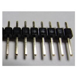
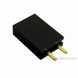
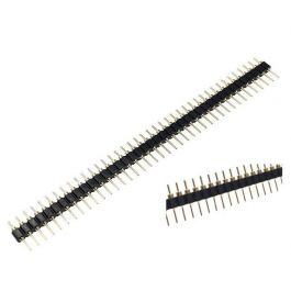
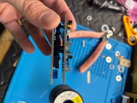
But I couldn't find a source for the 2-pin Female Headers 2.54mm, 2-pin Male Headers 2.54mm, or the 6-pin Male headers. Suggestions very much appreciated. The fundamental problem is that I don't know what I am looking for (physically) so it's tough to find things when I don't know what they are supposed to look like.

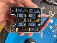
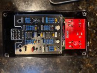
The other thing is that there doesn't seem to be actual build instructions that accompany most of the other pedal PCBs I have built in the past. It isn't obvious to me where the headers go. So, I would appreciate some guidance there as well. I presume the headers are used to join the two boards, but that's about as much of an assumption as I am comfortable in making.

Thanks in advance for any and all advice, suggestions, and assistance.

Bud
 
I haven’t built mine yet, but pretty sure I ordered the headers from Tayda.

Edit:

From the main tayda menu - Connectors and Sockets, then Pin Headers should get you to the right section
 
You want the ones that say they are 2.54mm spacing.


The way I like to do it is put the female one on the face of the bottom PCB (the one with the pots), and then the male pins on the bottom of the top pcb.

I like to put the male/female pins together, then tack one pin on each side, and make sure it looks lined up before soldering the rest.

Also, use the search in the build reports sub-forum and see if you find some visual examples. Maybe even in the troubleshooting sub-forum.
A lot of them say 2.54. I am sure you think I am an idiot, which is alright, because I think the same thing. Would you please indicate specifically which ones you use for the two-pin male, which for the two-pin female, and which for the 6-pin male? I sure can't figure out which ones to use. Thanks again. - Bud
 
I haven’t built mine yet, but pretty sure I ordered the headers from Tayda.

Edit:

From the main tayda menu - Connectors and Sockets, then Pin Headers should get you to the right section
I found the right section. Now if I only knew specifically which ones I need....
 
A lot of them say 2.54. I am sure you think I am an idiot, which is alright, because I think the same thing. Would you please indicate specifically which ones you use for the two-pin male, which for the two-pin female, and which for the 6-pin male? I sure can't figure out which ones to use. Thanks again. - Bud

For the male headers I’ve always bought the breakable 40 pin strips and cut off whatever I needed.


For female ones I’ve usually bought the pre made ones like this


But now I see that they also have breakable female ones, so I’ll probably just order some of those next time.


Also, looks like they’re mostly available in gold plate or not depending on how fancy you’re feelin.

As long as whatever you get is single row, 2.54, and not “right angle” (the ones with the bent pins, you should be good.

I’ve also made a 4 pin female work in a three pin spot by pulling the 4th socket out of the housing with pliers.
Just what I needed. Thank you so much! I was wondering if I could just break off what I needed, so that clarified that issue. I am very grateful for your excellent assistance. - Bud
 
I needed to order some from Mouser so used these Samtec part numbers for the 2-pin:

TSW-102-07-L-S
SSW-102-01-L-S
I will have to keep these in mind, since, of course, I just completed and paid for the Mouser order. I figured I would find what few items remained on Tayda, which I did, but Mouser gets here faster so there's that. Thanks very very much! - Bud
 
Definitely use the good headers that EriK S said. They are very sturdy. I built this a few weeks ago and it’s great. The other thing to notice is q6. It’s BC560. You may or may not find it but make sure you are aware that it’s NOT BC550 like the others. Its’s very easy to miss. I didn’t have one so I used 2n5087 which is a great substitute that is easy to find. Just make sure your turn it 180 degrees from the screen print.
 
I read through your post again and have some other tips for this one. Build the top and bottom boards just like you would any other board. Populate the items from small to large. Do not do the headers until both boards are completely loaded (except Ic’s). Once both boards are populated its time for the headers. The way i do it is to use the female header pin for the bottom board and the header strip for the top board. The easiest way to assemble it is to place the long pins of the header strip into the female header so they are one piece. Place all of them on the bottom board (do not solder yet) and then line up the top board with the headers and place it on top. Check and make sure everything is as straight as possible and you have no clearance issues then solder the top then flip the whole thing over together and solder the bottom. It should look like this.
 

Attachments

  • IMG_5075.jpeg
    IMG_5075.jpeg
    325 KB · Views: 3
  • IMG_5076.jpeg
    IMG_5076.jpeg
    261.8 KB · Views: 3
  • IMG_5098.jpeg
    IMG_5098.jpeg
    405.3 KB · Views: 3
I typically use internal lock washers on 16mm pots, but on stacked board pedals, I now exclude them. It does make a bit of difference on the clearance between the top board and the enclosure lid.
 
Back
Top