Caesar Chorus no LFO

mkultra69

Member
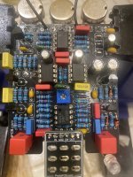
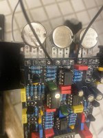
Got everything put together and the good news is I get signal passing through the pedal when engaged, bad news no rate LED and no noticeable effect. I can kinda hear something when turning the pots up and down, but its pretty much nothing. I think there is an issue with IC1 as its voltages are pretty out of wack from what Ive seen others post. Heres the rundown.

IC1:
1-8.13
2-.669
3-3.74
4-0
5-.669
6-2.97
7-.684
8-8.83

IC2:
1-6
2-6
3-6
4-0
5-6
6-6
7-6
8-8.93

IC3:
1-0
2-4.27
3-5.5
4-8.26
5-8.83
6-4.25
7-7.2
8-7.2

IC4:
1-8.83
2-4.25
3-0
4-4.27
5-.274
6-8.5
7-2.33
8-8.26
Caesar.JPG
 
The lack of rate LED is concerning. The trimpot has to be biased to get effect but the rate LED should be going regardless. Is the blend pot insulated from shorting out the back of the pcb?
 
First thing I see is something really funky with VREF_B. That should be ~4.5V direct to pins 2 and 5 of IC1.
I'd check anything around there, specifically - your divider resistors look correct but you might want to doublecheck.
Also any component that takes VREF_B - e.g. the rate+depth pots, and maybe especially the caps you added in place
of the LEDs - are those okay? You could probably eliminate those as a suspect if the voltage is the same regardless
of the switch position.

What are the voltages on the socket if IC1 isn't in there? That might help narrow it down.
 
Thanks for the ideas, definitely something off with VREF_B. Without the IC in I get the following:
1-.7mv
2-1mv
3-.7mv
4-1.1mv
5-1mv
6-.7mv
7-.7mv
8-8.89v

checking R100, and R101 I get 8.87v on both sides of R100 and .672v on one side of R101 and 0 on the other. Also getting 8.86v on the + side of C103
 
It sounds like one of the legs of either R100 or R101 are not soldered, or the trace between R100 and R101 is broken. Probably whatever leg of R100 connects to R101, given that all of your VREF_Bs also seem to be floating and/or ground. You should be getting R100 = 8.8/4.4 and R101 = 4.4/0. It could also be (unlikely?) that R100 is bad - what are the resistance measures between the various legs?
 
Not sure you can get a good R reading on R101 and C103 is in parallel.
Getting full vcc on both sides of R100 indicates either R100 is short or VrefB is shorted to ground. Or possibly R100 is open and the impedance of the DMM is masking it, hence the reading just below VCC.
Reflow R101, left side(component side) looks cold.
Inspect all points VrefB is used for a solder bridge. Can also check VrefB resistance to ground, which I'm guessing is near zero.
C103 could be a short as well.
 
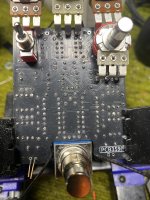
I reflowed both 100, and 101 to no avail. For what its worth I tested both resistors and got ~10k across each and ~20k across both. Shouldn't I be getting VREF_B at pin 2 and 5 even when the chip is pulled? Here is a pic of the back, so much for the lint free cloth lol IMG_6500.JPG
 
Back
Top