You are using an out of date browser. It may not display this or other websites correctly.
You should upgrade or use an alternative browser.
You should upgrade or use an alternative browser.
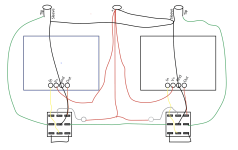
Can anyone critique this wiring layout?
- Thread starter jojofogarty01
- Start date
jojofogarty01
Member
Specifically my grounding. I feel like I'm missing something obvious that will make it way more straightforward.
BuddytheReow
Moderator
Looks ok to me. It's pretty much this plus the LEDs. https://wiki.pedalpcb.com/wiki/2-in-1_Pedal_Wiring Are you building stripboard or other PCB for the two effects?
jojofogarty01
Member
Its two PCB's from Effectpedalkits.com I picked them over PedalPCB for this pedal because his are more compact and allow for offboard potentiometer wiring. I just wish he had included a couple extra ground pads so I'm not struggling to fit multiple wires through one pad. The LED's I have in the diagram I posted, they're the little grey circles.Looks ok to me. It's pretty much this plus the LEDs. https://wiki.pedalpcb.com/wiki/2-in-1_Pedal_Wiring Are you building stripboard or other PCB for the two effects?
BuddytheReow
Moderator
I figured that for the LEDs. Does the board not come with them ready to solder in?
benny_profane
Well-known member
Double up the GND connection at the switch rather than the board pad. Also ensure you have CLRs for the LEDs.
jojofogarty01
Member
No, LED's on these are off the board.I figured that for the LEDs. Does the board not come with them ready to solder in?
Yep I've got them In front of the LEDs, just didn't feel like putting them in the diagram. Also good suggestion with the Ground wires.Double up the GND connection at the switch rather than the board pad. Also ensure you have CLRs for the LEDs.
DGWVI
Well-known member
jojofogarty01
Member
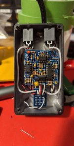
I would use a 3pdt breakout but the holes in my 2-in-1 enclosure for the switches are so close to the edges that they won't allow space for one.Heads-up- the FuzzDog 3pdt boards align with these, and have a spot for board mounted LED
Also came to say this.
View attachment 38779
DGWVI
Well-known member
Those particular 3pdt boards are the same width as the switch baseI would use a 3pdt breakout but the holes in my 2-in-1 enclosure for the switches are so close to the edges that they won't allow space for one.


