Can someone please help with this old Green Russian veroboard? Need someone who has circuit understanding 😅

Sheesh, okay so here goes. I wanted to build a green russian but opted for an alternative layout because I don't have the right cut of veroboard for the bigger one.
Here's the schematic, following this diagram is two questions I need help with

green russian big muff stripboard veroboard layout.gif

So i have two questions

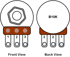
1. Can someone please clarify which direction I should read the pots?

What gives me pause here is that either volume 3 is going to ground or sustain 3 is going to ground, I have a limited understanding that pots should have terminal 1 going to ground, so if anyone can help here that'd be great? Do I read these as 3-2-1 or 1-2-3?

2. I'd love to shoehorn this tone switch into this build, but I'm unsure how
Specifically where would SW1 be in the schematic above? and, would the other end of the switch still take Tone 3?
EHX Green Russian Big Muff V7 1994.png

Thank you very much
Kyle
 
Pots:
Potentiometers-front-back.png

Sustain 1 goes to ground, Volume 3 goes to ground.

Tone:
It's early so let's see if I get this right. You want to make C10 switchable like in the second vero.
The switch goes in the place where you have the Tone 3 connection to the vero. On pole of the DPDT goes to Tone 3, the other pole goes to where Tone 3. Then, replace C10 with a jumper.
Thanks, does Volume 3 to ground seem right to you? I have a feeling it's a 'typo' but I'm not sure enough
 
Also @szukalski here’s a bit more info on the mid boost switch, I think this should add into the other cap in parallel

“The centre off position leaves just the 4n on its own which is as per the original circuit. One position adds the 4n7 in parallel to give you 8n7 which is the flatter response, the other adds the 10n to give you 14n for the boosted mids position. That's what I like about this switch, you can keep everything authentic if you want, and boost if you need to.”
 
Thanks, does Volume 3 to ground seem right to you? I have a feeling it's a 'typo' but I'm not sure enough
I'd have to go through the schematic to know, sorry. But in general I'd expect 1 to ground. Both will work, but one will seem backwards.
Also @szukalski here’s a bit more info on the mid boost switch, I think this should add into the other cap in parallel

“The centre off position leaves just the 4n on its own which is as per the original circuit. One position adds the 4n7 in parallel to give you 8n7 which is the flatter response, the other adds the 10n to give you 14n for the boosted mids position. That's what I like about this switch, you can keep everything authentic if you want, and boost if you need to.”
Then leave C10 in.
 
Pot numbers.png

In any Big Muff I've built Vol 1 goes to ground. The layout above by Tim Webster has the lugs of the Vol pot the wrong way around.

As far as where to connect the mids switch, you can see that "Switch 1" goes to the collector of Q3. So on the Webster layout that would be 23E on the grid. If you use that layout you won't be able to fit it into a 1590B enclosure - you'll need a 125 at least. You might need to increase the width of the board by 1 row as well if you want to connect the switch to the collector of Q3.

The thing about these layouts is that as long as everything that needs to connect with other parts does, and things that shouldn't connect don't you can arrange it any way you like. I think IVIark's layout is better than Tim's because the wiring is all connected at the edges. It doesn't have to but is a lot neater if it does. BTW these drawings are not schematics, they are layout diagrams. Tim's layout is a bit clumsy and I'm not sure how reliable it might be. You might even be able to use IVIark's layout and just substitute the values in Tim's.

BTW you will see in IVIark's layout that he has connected Volume 1 to the board where it will be in contact with ground. You can do it that way or simple wire lug 3 of the Volume pot to a ground point anywhere in the enclosure. I usually connect it to the output jack.
 
Thanks so much @HamishR , honestly it all came down to the fact that I didn’t have veroboard that size, I searched for a GM but smaller and that’s what I found haha. This is my first go at vero other than small boosts so this is really enlightening, thanks mate
 
Last edited:
Back
Top