Untro
Member
Hey all,
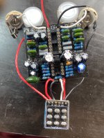
So after boxing up my second Cataclysm, I was feelin pretty confident. Plugged it in, and got a horrible distorted squealing! I could barely make out an idea of a delay underneath a constant high pitched feedback which continuously dropped in frequency, until it just passed regular signal. I turned it on and off again, it made dry signal when engaged for a moment, and then completely stopped passing signal.
I tried taking it out, reflowing a few points (which might have done more harm then good tbh, everything seemed fine...), popped it back in with a new set of IC chips and gave it a go, same results. I am fairly convinced that this is the sound of a PT2399 chip dying an excruciating death.
So far all my issues have been user errors and outboard wiring, but I'm a little confused on this one. Troubleshooting circuits is still a skill I lack. I tried reading voltages from the PT2399, which I can report later if relevant. Any help is very welcome!
A few things to note: I installed the TL072 socket backwards, but made sure to put it in right. That shouldn't matter, right?
The IC chips are from Tayda, so I've tried two PTs and more 072s. The first Delay i made with a PT worked fine, though!
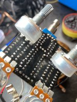
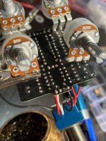
And yes, I cleaned the breakout board after taking this picture lol. I need a better alcohol/cleaning setup...


