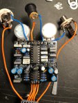
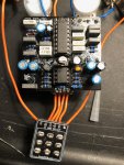
Cataclysm Delay passes sound but doesn't turn on

I completed my build (second ever) and plugged everything in. I got sound when in bypass but nothing happened when I switched the pedal on. I thought maybe I had put the LED in the wrong way so I switched that around and tested again and that time I had signal through the pedal both in by pass and when engaged, but the LED didnt light and there was no effect present. I am unfortunately waiting on my multimeter to arrive so I am unable to use that to test at the moment. I am just wondering if there is an obvious issue with my build.

Also, now that I am not sure which way my LED actually is in, I was going to start with a fresh one but all I have is a two color LED with three legs. Is there any way to use this one as a single color by using only two of the legs?
Thanks in advance. IMG_4279.jpg IMG_4285.jpg IMG_4282.jpg IMG_4281.jpg IMG_4279.jpg
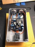
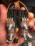
 
update: well I got it to work after taking it out of the enclosure, reseating the transistor and flipping the LED around. Unplugged it, went to put everything back in the box, resoldered the DC jack and it isn't working again. At least I know it CAN work.
 
Does the led work in the enclosure?

By answering that you could narrow it down to a power issue. I’d recommend putting some solder on the regulator legs where it meets the socket (transistor packages can be trusted to stay in sockets). But if it was just a problem with the regulator, you’d still get dry signal through, but it sounds like it’s silent when engaged, right?

Try gently wiggling any of the wires (those ground wires on the top of the pcb have a lot of metal exposed) to make sure the wires aren’t hitting each other. Maybe also try wiggling the tl072, those socket are less reliable, for the future I recommend machines type sockets for chips (machines types have the round metal holes like the socket your regulator is in).

If you narrow it down to signal, not power (like if the led works but there’s no sound, you could make an audio probe and try to find where you lose the signal. And when you get the multimeter, check for voltages on the chip pins and report back.


Hey thanks for the suggestions and the help, I REALLY appreciate it. I was able to get it working by adding a little solder to the legs of the transistor, and re-soldering my power connections. I also appreciate the tips for my next builds. This was the first one that I have built where I sourced my own parts instead of working from a kit. Any feedback about better components or methods will help me for future builds. I had a bit of trouble getting the transistor into the socket, in the future is it ok to just solder that to the board rather than using a socket? Also, as far as you can see, does my soldering seem relatively ok (besides the exposed wires at the top of the board, I will have to pay attention to that next time)?
 
Glad it’s been working. For power regulators I always just solder it straight in. I do sometimes socket transistors, if it’s a crucial part of the audio path and/or a finicky part (jfets, ge transistors) where I might want to experiment. But I always add just a bit of solder to the pins before boxing up because they do fall out.

I always socket ICs for a couple reasons
1. No heat on the ics while populating the board.
2. Makes quick troubleshooting if you suspect a bad ic (almost never is though)
3. Some dirt pedals sound different with different chips so you can experiment.
4. Pt2399 chips have a range of performance (noise/tone), so I always socket and try a few.
5. I’ve never had a chip fall out or lose contact with the machines type of socket.

Great advice! I did add some solder to the pins to make sure it was making good contact. Really good advice on the PT2399, I have noticed that there seems to be some background noise on the repeats, sort of a "wooshing" thing, which isn't awful but I may try a couple different ones to see if I can clean it up a little bit.

This may also be a dumb question, but how can you tell if it is a power regulator or in the audio path? Is that something that you can tell just by which type of component is used, or is it from looking at the schematic/you just know from experience?
 
Yeah all of the above, look up what the component is/does. Try to read the schematic.

This article breaks down a belton brick reverb circuit, but it has a lot in common with the most pt2399 delays.

 
Yeah all of the above, look up what the component is/does. Try to read the schematic.

This article breaks down a belton brick reverb circuit, but it has a lot in common with the most pt2399 delays.


Great, thanks again!
 
Back
Top