CDXL Classic distorting

scheffehcs

Well-known member
Hello. I got started building pedals over winter and I’m just now revisiting the ones that didn’t work.

I pulled out the CDXL Classic envelope filter and immediately realized that the IC was upside down (TL072, luckily socketed). So I grabbed a new one and plugged it in.

The result is that I’m getting effected signal, but it’s pretty gnarley sounding. Here’s the video.


Looking for any advice for how to diagnose and fix the pedal, still very amateur in that regard. I’m gathering that being able to read schematics is the first step. I have a signal tester and multimeter, but I just don’t know where to start.

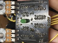
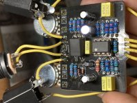
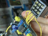
Thanks. Here are some pics of the board.
937B686D-9884-43B7-A040-01636D58EFF0.jpeg F65B60F2-078C-455E-BAA0-D91AB185DFDB.jpeg CA0F6171-E063-4394-B2BA-3189CBAD6DE0.jpeg
 
If you are familiar with tracing circuits based on the schematic and have an audio probe, that may help. I haven't built this pedal, but it isn't too hard to trace per the schematic.
 
Hello. I got started building pedals over winter and I’m just now revisiting the ones that didn’t work.

I pulled out the CDXL Classic envelope filter and immediately realized that the IC was upside down (TL072, luckily socketed). So I grabbed a new one and plugged it in.

The result is that I’m getting effected signal, but it’s pretty gnarley sounding. Here’s the video.


Looking for any advice for how to diagnose and fix the pedal, still very amateur in that regard. I’m gathering that being able to read schematics is the first step. I have a signal tester and multimeter, but I just don’t know where to start.

Thanks. Here are some pics of the board.
View attachment 5806View attachment 5807View attachment 5808
Mine does the same noises. I’ll try and trade the signal for mine and see if I can find what the issue is.
 
You could try a temporary 500k pot as a variable resistor & remove R5 - 430K & adjust to see if it clears up the distortion by unloading the OpAmp.
Just solder a Hook Up wire to Leg 1 of the pot & another Hook Up wire to Leg 2. Measure with DMM to get 430k to start with!
Attach 1 lead to to each R5 pad of the removed Resistor.
If you find the sweet spot & it appears to be working correctly, Don't knock the pot & remove from pads & measure with a DMM to get the Resistor
value between the 2 Hook up wires.
This PCB has been a Thorn in the side for anybody that has tried to build it!!!
 
Ok I see what you’re saying. I’ll give it a shot. Thanks!
You could try a temporary 500k pot as a variable resistor & remove R5 - 430K & adjust to see if it clears up the distortion by unloading the OpAmp.
Just solder a Hook Up wire to Leg 1 of the pot & another Hook Up wire to Leg 2. Measure with DMM to get 430k to start with!
Attach 1 lead to to each R5 pad of the removed Resistor.
If you find the sweet spot & it appears to be working correctly, Don't knock the pot & remove from pads & measure with a DMM to get the Resistor
value between the 2 Hook up wires.
This PCB has been a Thorn in the side for anybody that has tried to build it!!!
 
Back
Top