DEMO Chalumeau (clean)

This post contains an audio or video demo

DGWVI

Well-known member
Build Rating
5.00 star(s)
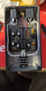
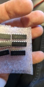
Used an HT8970 for the delay chip. Lifted both pins 1 and 8 of the 386n-4. 9203 LDR, ultrabright diffused red LED for the envelope bit. This one's pretty fun. Can do some subtle stuff, but it excels at wacky, sort controllable pitch shifting
I'd liken it to a deranged cousin of the Low Tide. These would probably sound awesome together
received_524341033137553.jpeg
 
sounds very good !
i just finished my build as well. Was wondering how one can make it a clean edition ? I was thinking ot use this pedal for mixing process and by twisting the Blend all teh way to wet signal only use it on a send / return fx chain.
another thing - is it normal that the wet signal is picking up a lot of dirt sound ? I don't know where and what affects it in the circuit but it would be nice to know, mine also picks up radio interferences (although I kept the legs of all caps very short an close to pcb).
Also according to your gut photo - seems like I put my potis wrong so maybe it explains why volume and blend react in a reverse way (ccw) then usual ?

thanks!
 
one more question about the LDR - how can I tell which resistance values does my LDR ranges from ? the build notes and bill of materials doesn't say which tape of LDR is recommended to be used.
 
ok so by lifted pin 1 & 8 of the 386n IC - I assume you omit the op-amp part which makes it fuzz (not clean) ? I think I now see it clearly from your gut photo (not sure though, could be an optical illusion..)
im slowly getting back to my knowledge of pedal building.. its been some years off :)
 
then again - what does using a HT8970 instead of a PT2399 is doing for the echo and it's sound ?
thanks once again and sorry for all the questions - this is right now on my building desk :)
 
sounds very good !
i just finished my build as well. Was wondering how one can make it a clean edition ? I was thinking ot use this pedal for mixing process and by twisting the Blend all teh way to wet signal only use it on a send / return fx chain.
another thing - is it normal that the wet signal is picking up a lot of dirt sound ? I don't know where and what affects it in the circuit but it would be nice to know, mine also picks up radio interferences (although I kept the legs of all caps very short an close to pcb).
Also according to your gut photo - seems like I put my potis wrong so maybe it explains why volume and blend react in a reverse way (ccw) then usual ?

thanks!
ok so by lifted pin 1 & 8 of the 386n IC - I assume you omit the op-amp part which makes it fuzz (not clean) ? I think I now see it clearly from your gut photo (not sure though, could be an optical illusion..)
im slowly getting back to my knowledge of pedal building.. its been some years off :)


For this one, I bent legs 1 & 8 of the 386 so they sit just outside of the socket. It'll still have a sizable boost, and be able to overdrive and distort anything downpath from it, so it's not perfectly clean

You can also omit R1 and C4 if you decide you don't ever want the fuzzy bits

Looks like you've mounted all of your pots backward. The Volume and Blend pots should behave as most other pedals, while the Depth, Tracking, and Delay pots will work in reverse of how we'd typically expect

As for the radio interference, I can't help there as it's not issue I've run into. I'm guessing the gain of the 386, and being out of the box are playing a role

one more question about the LDR - how can I tell which resistance values does my LDR ranges from ? the build notes and bill of materials doesn't say which tape of LDR is recommended to be used.

To check the resistance range of your LDRs, use a multimeter set for resistance, take one measurement with the LDR completely blocked off from any light source, and another with a bright LED shining directly at it. Should give you a decent idea.
Do you know which LDRs you're using?

I used 9203s in this one- I like their wide range and quick response times


then again - what does using a HT8970 instead of a PT2399 is doing for the echo and it's sound ?
thanks once again and sorry for all the questions - this is right now on my building desk :)

The HT chip has a lower minimum delay time, and starts to distort earlier the higher the delay time is turned up. Works a little better in circuits geared toward chorus and vibrato sounds, in my experience
 
thanks for all the tips!
and I assume the echo chip can simply be replaced (HT instead of PT) in the same position without any further adjustments to the PCB right ? simply pop in and out and see which sounds better to my taste ?
I dont know which LDR I am using no, and now - since it's built already and also implemented within a heat shrink attached to the LED - the only way to find out would be to break it up and do the testing as you suggested.
I think I will skip this as I dont hear anything I dont like from the wobblyness and (I guess can be reffered to as?) 'tacking'.
maybe a cool project would be to implement several LDRs with different LEDS and toggle between them. Heck knows how to plan it though cause of the need for it to be in a dark space.
I will start off with trying to make it sound clean - do you think there is a way to put a switch there to toggle between the clean and distorted mods ?
thanks!
Yes- the HT is pin compatible and requires no other adjustment

As for a clean/ fuzz toggle, I'd suggest just lifting pin 8 and putting an SPDT toggle between the pin and the socket or board hole
 
SPDT - those with 3 lugs right ? so one side just connected to pin 8, the middle lug to the board and the other side of the switch not connected - right ?
 
perfect. Ill try to do another video of how it sounds like. very nice. I do totally get waht you mean though with PT2399 is rather dirty signal.
I think I will simply build another one where the IC is the HT chip.
Would be awesome to have a mod where you can toggle between the 2. but I guess there is no end for the wishes :)
 
Back
Top Bottom