Idlebeach
Member
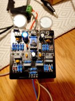
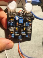
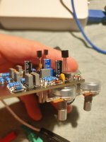
I just built the Champ Stamp and while it functions and sounds pretty good I have a couple questions about the trimmer/ biasing the J201
Has anyone else built the Champ Stamp and happen to know what the trimmer should be set to? It seems to be biasing a transistor other than the J201. I don't know if the transistor it's changing can get to 4.5 so I'm not sure what to set it to.
Also, does the J201 need to be biased? I would've assumed it should just be 4.5 but I'm not sure which resistor I would need to swap out to make that happen.
Thanks for your time everyone!


