Chaos Machine

Mike52

Active member
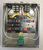
This should have been a buggy, frustrating build but looking back it went off without a hitch. It seemed like a great noise rock pedal (based, I'm assuming on the discontinued EQD Interstellar Orbiter) that I bought on a whim. I put it together very straightforward but if I had it to do over again I would have studied @Chuck D. Bones excellent threads on LFOs and would have identified areas of the circuit to tweak and then socketed those locations. As this was my first attempt at a noise pedal I just did it straight from the instructions.

The only thing I can think of to criticize about either my build or this circuit is probably the "Direct" dial. That is supposed to mix the dry guitar signal in with the filter circuit and to my ears it is doing something but it never gets completely dry. Maybe I did something wrong. Does any other Chaos Machine owners know if that pot will let you get to a 100 percent dry signal?
top.jpg

If anyone has recommendations as to what components should be socketed, that would be much appreciated. It seems like you could easily install a couple of trim pots in place of resistors but I'd be worries about doing that myself since the LFO circuit is, by design, a Cat's Cradle and small changes here have downstream effects that may cause the pedal to quit working. I just wanted to get to the point of playing this so didn't mess around. But I would love to have a deeper understanding of the circuit.

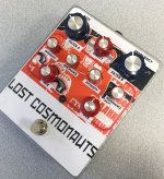
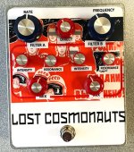
The art was basically a white vinyl sticker as a background and then a clear vinyl sticker with the colors. "Lost Cosmonauts" was a free font that I found online. I can't remember what connection it had to Russian propaganda posters, but I think it was a font commonly found on them. The rest of the art is just a Russian Propaganda poster of their space program with a few faces blocked out to give the pop art effect I was looking for.

Anyway, this was actually a smooth build. I'd read many troubleshooting threats about ticking problems, but for whatever reason I never encountered them. So, I guess I got lucky.

cosmo.jpg
 

Attachments

  • maingut.jpg
    maingut.jpg
    224.6 KB · Views: 84
Last edited:
I’m looking to build one of these myself and did a little research. Apparently even the original has issues with the Direct knob. Seems it’s rather subtle. Not the end of the world but I am curious on how it could be improved.

 
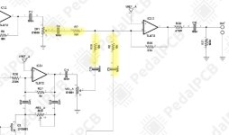
Exactly. This would be an amazing pedal if you had the ability to dial it back from 100% dry to the point where you just barely perceive the tails of the resonant filter kicking in. I wonder if there is a way to adjust the values of C4-R7 and R28-C15 and R8-C5 to allow more of the dry signal through. Hmm. Hopefully someone who understands LFOs can explain to me why this would not work.

schematic.jpg


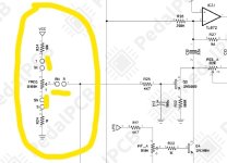
IT looks like C3 and the Dry pot are a high pass filter and the C4and beyond are voltage dividers and low pass filters? Is that correct? (actually that's probably all wrong). Hmm. The Boss CE-2 chorus uses a summing amp at the JRC4558 IC and has an emphasis filter both pre and post to fix the dry signal at about 50 percent.


I don't think that's what is going on here. In fact I don't think I understand what is happening at this location in the circuit. I see both high pass and low pass filters and voltage dividers but I would think that the dry signal output would be affected by both of the mix knobs. Maths is hard.
 
Last edited:
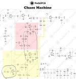
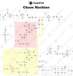
Not to belabor this too much, but can anyone explain what is happening to the signal as it passes filter circuits A and B? I am pretty illiterate when it comes to reading these circuits. I'd sure appreciate understanding this pedal a bit better.

I've called out what I can see as the only differences in the circuit, but really can't interpret what they are doing to the signal.

chaos_small_LI.jpg
 

Attachments

  • chaos.jpg
    chaos.jpg
    216.6 KB · Views: 6
Last edited:
I’m looking to build one of these myself and did a little research. Apparently even the original has issues with the Direct knob. Seems it’s rather subtle. Not the end of the world but I am curious on how it could be improved.

This may be a way to improve it.
 
Last edited:
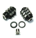
I'm getting ready to see if if I need to order any parts for this build (I think I might have ordered parts a few months back and then hesitated on starting the build due to it's complexity). As I look over your thread, the one part I wish I could see and am nervous about is wiring up the expression jacks. Any chance you have a picture of how you wired those from before you got them situated the way they ended up in the box? Or could you maybe use this image and label the pinout somehow?

stereo switched jack.jpg

I would be super grateful. Keeping track of which pin is which on jacks like this is one of my weak spots. I constantly double and triple check them as I solder the wires and I still make mistakes some of the time.
 
I'm getting ready to see if if I need to order any parts for this build (I think I might have ordered parts a few months back and then hesitated on starting the build due to it's complexity). As I look over your thread, the one part I wish I could see and am nervous about is wiring up the expression jacks. Any chance you have a picture of how you wired those from before you got them situated the way they ended up in the box? Or could you maybe use this image and label the pinout somehow?

View attachment 20408

I would be super grateful. Keeping track of which pin is which on jacks like this is one of my weak spots. I constantly double and triple check them as I solder the wires and I still make mistakes some of the time.
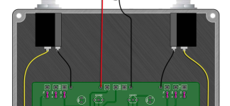
Unfortunately, I don't have a better picture. But it's actually pretty intuitive if you study the wiring diagram (page 4). As you look at the input socket you can see a contact blade spanning across to join each pair of the solder lugs. When you plug a jack in, it lifts that blade and breaks contact. The side where the blade breaks contact is the switched side.

The instructions tell you that if you don't want an expression out then just solder jumpers across the tip, ring, sleeve with their respective "switched" counterpart (page 5). That's effectively what you have when nothing is plugged into the socket, a jumper across each.

Find the "switched" side of the input socket, and wire it accordingly. Sleeve is found nearest the input socket, tip is found furthest from the opening. When there is nothing in the socket, the circuit is closed and the signal travels to the Frequency and Rate pots respectively. When the blades lift, the circuit is broken and the signal is diverted through the tip, ring and sleeve onto the expression pedal.

Inkedexpression_LI.jpg

I screw up simple things all the time, but wiring this up actually went pretty smoothly.
 
I'm getting ready to see if if I need to order any parts for this build (I think I might have ordered parts a few months back and then hesitated on starting the build due to it's complexity). As I look over your thread, the one part I wish I could see and am nervous about is wiring up the expression jacks. Any chance you have a picture of how you wired those from before you got them situated the way they ended up in the box? Or could you maybe use this image and label the pinout somehow?

View attachment 20408

I would be super grateful. Keeping track of which pin is which on jacks like this is one of my weak spots. I constantly double and triple check them as I solder the wires and I still make mistakes some of the time.
That's why I don't use jacks that look like that
 
Exactly. This would be an amazing pedal if you had the ability to dial it back from 100% dry to the point where you just barely perceive the tails of the resonant filter kicking in. I wonder if there is a way to adjust the values of C4-R7 and R28-C15 and R8-C5 to allow more of the dry signal through. Hmm. Hopefully someone who understands LFOs can explain to me why this would not work.

View attachment 19039


IT looks like C3 and the Dry pot are a high pass filter and the C4and beyond are voltage dividers and low pass filters? Is that correct? (actually that's probably all wrong). Hmm. The Boss CE-2 chorus uses a summing amp at the JRC4558 IC and has an emphasis filter both pre and post to fix the dry signal at about 50 percent.


I don't think that's what is going on here. In fact I don't think I understand what is happening at this location in the circuit. I see both high pass and low pass filters and voltage dividers but I would think that the dry signal output would be affected by both of the mix knobs. Maths is hard.
Technically those are all high pass filters. That is, they remove DC offsets from the three preceding stages. There is no mod possible to these to increase the amount of dry signal. This is not a blending but a mixing circuit, where the volume of each signal is controlled by dry, mix A and B. The only way to have more dry and less of anything else is to lower mix A and B.
 
Technically those are all high pass filters. That is, they remove DC offsets from the three preceding stages. There is no mod possible to these to increase the amount of dry signal. This is not a blending but a mixing circuit, where the volume of each signal is controlled by dry, mix A and B. The only way to have more dry and less of anything else is to lower mix A and B.
That is slowly dawning on me, as well as the distinction between "mixing," "blending" and "panning." This project inspired me to begin building a three channel signal blender pedal (two effects, one clean, like the Old Blood Noise Signal Blender). I'm in the middle of sorting all that out still. It is a more complicated ask then I first thought.
 
Last time I checked Mr @PedalPCB was working on tracing the EHX parallel mixer which does basically the same. Maybe we can get some good news? I’ve been waiting for that one!
 
This should have been a buggy, frustrating build but looking back it went off without a hitch. It seemed like a great noise rock pedal (based, I'm assuming on the discontinued EQD Interstellar Orbiter) that I bought on a whim. I put it together very straightforward but if I had it to do over again I would have studied @Chuck D. Bones excellent threads on LFOs and would have identified areas of the circuit to tweak and then socketed those locations. As this was my first attempt at a noise pedal I just did it straight from the instructions.

The only thing I can think of to criticize about either my build or this circuit is probably the "Direct" dial. That is supposed to mix the dry guitar signal in with the filter circuit and to my ears it is doing something but it never gets completely dry. Maybe I did something wrong. Does any other Chaos Machine owners know if that pot will let you get to a 100 percent dry signal?

View attachment 19036

If anyone has recommendations as to what components should be socketed, that would be much appreciated. It seems like you could easily install a couple of trim pots in place of resistors but I'd be worries about doing that myself since the LFO circuit is, by design, a Cat's Cradle and small changes here have downstream effects that may cause the pedal to quit working. I just wanted to get to the point of playing this so didn't mess around. But I would love to have a deeper understanding of the circuit.

The art was basically a white vinyl sticker as a background and then a clear vinyl sticker with the colors. "Lost Cosmonauts" was a free font that I found online. I can't remember what connection it had to Russian propaganda posters, but I think it was a font commonly found on them. The rest of the art is just a Russian Propaganda poster of their space program with a few faces blocked out to give the pop art effect I was looking for.

Anyway, this was actually a smooth build. I'd read many troubleshooting threats about ticking problems, but for whatever reason I never encountered them. So, I guess I got lucky.


View attachment 19038
Really great job on the build! Did you drill the holes yourself or did you have a template to go off of?
 
Really great job on the build! Did you drill the holes yourself or did you have a template to go off of?
Yeah, I just used the paper template PedalPCB provided and printed it at actual size. But I'm sure you could rearrange the knobs any way you want, ala Fairfield Circuitry. The box is cavernous.
 
This should have been a buggy, frustrating build but looking back it went off without a hitch. It seemed like a great noise rock pedal (based, I'm assuming on the discontinued EQD Interstellar Orbiter) that I bought on a whim. I put it together very straightforward but if I had it to do over again I would have studied @Chuck D. Bones excellent threads on LFOs and would have identified areas of the circuit to tweak and then socketed those locations. As this was my first attempt at a noise pedal I just did it straight from the instructions.

The only thing I can think of to criticize about either my build or this circuit is probably the "Direct" dial. That is supposed to mix the dry guitar signal in with the filter circuit and to my ears it is doing something but it never gets completely dry. Maybe I did something wrong. Does any other Chaos Machine owners know if that pot will let you get to a 100 percent dry signal?

View attachment 19036

If anyone has recommendations as to what components should be socketed, that would be much appreciated. It seems like you could easily install a couple of trim pots in place of resistors but I'd be worries about doing that myself since the LFO circuit is, by design, a Cat's Cradle and small changes here have downstream effects that may cause the pedal to quit working. I just wanted to get to the point of playing this so didn't mess around. But I would love to have a deeper understanding of the circuit.

The art was basically a white vinyl sticker as a background and then a clear vinyl sticker with the colors. "Lost Cosmonauts" was a free font that I found online. I can't remember what connection it had to Russian propaganda posters, but I think it was a font commonly found on them. The rest of the art is just a Russian Propaganda poster of their space program with a few faces blocked out to give the pop art effect I was looking for.

Anyway, this was actually a smooth build. I'd read many troubleshooting threats about ticking problems, but for whatever reason I never encountered them. So, I guess I got lucky.


View attachment 19038
Great build and artwork. I'm currently finishing mine up. I had a question for this group. Does anyone know how to wire the R, RN, T, TN, and S, SN without the expression inputs? From the wiring diagram-it looks like you just connect them together (attached file). Is this correct?

Thanks!
 

Attachments

  • Screen Shot 2023-07-03 at 2.31.30 PM.png
    Screen Shot 2023-07-03 at 2.31.30 PM.png
    1.3 MB · Views: 14
Back
Top