Cheese Monger: modding for more volume?

lumberjack

New member
Hey gang, first time poster here, and rather new to building in general.

I recently finished a Cheese Monger and absolutely love the sound and feel, but with the volume dimed I'm riiiight around unity, and depending on how I've got the tone set up, even with the volume maxed it can even seem like a bit of a dip in overall output. I read up on the original Big Cheese and found that was a issue for that circuit as well, but I wasn't sure how to go about getting a bit more clean output from the circuit.

The only idea I could track down was this: https://www.freestompboxes.org/viewtopic.php?f=13&t=13760

Just curious if someone with a bit more circuit know-how could chime in on this approach or any other that might prove useful. Thanks!
 
So one way to do it is do what AionFX did with their “Monolith” board and turn the unity-gain stage near the end into a boost stage:


To do this with the PedalPCB Cheesemonger board you’d need to cut the trace between pins 6 and 7, connect a resistor between them (33K is what Aion uses), then connect a smaller resistor and a capacitor (15K and 100n is what Aion uses) from pin 6 to ground.

I don’t like cutting traces because I never really trust myself to do it cleanly, so what I’d do and have done in the past is build this little stripboard LPB-1 and put it after the circuit to give it a clean post-boost.

 
Other boosts to consider tacking on would be the MXR Micro-Amp (compact build on vero or perf), or a simple JFET/MOSFET boost such as Jack Orman's AMZ dealio (again, on vero or perf) — check out tagboard effects, effects layouts respectively. You can find PCBs online for the aforementioned circuits.

Or you can explore PedalPCB's various compact boost offerings:

https://www.pedalpcb.com/product/blacktiger/ (Mr Black Tiger)
https://www.pedalpcb.com/product/pcb346/ (Aft, EQD Bows)
https://www.pedalpcb.com/product/amentum/ (EQD Arrows)
https://www.pedalpcb.com/product/cleaver/ (Keeley Katana)

IF you're not trying to conserve space, or are open to a dual-sized build then there are even more options such as the Ember etc...
https://www.pedalpcb.com/product/emberboost/ (TC Spark, the large one)

 
Awesome, this is perfect info guys I really appreciate it! I'll probably try that output-buffer-to-boost conversion thing first as it's the simplest/quickest looking solution, but it's nice to know I can just tack on a recovery/boost stage like that onto (almost?) any circuit.

I'm coming from the tube-amp-building side of the electronics world, and as helpful as it's been to bring some of that general knowledge along for the pedal building ride, I'm finding I have looooots to learn about how these small signal/voltage circuits function. Much appreciated fellas, I'll try this out today and report back.
 
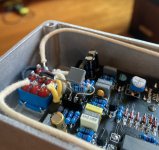
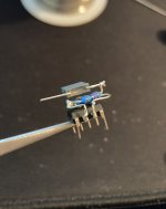
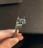
F970A6EB-55B6-4ACE-8AB3-8B2A9A3CFCBA.jpeg The Aion modification to the second tl072 section worked like a charm! I have a bunch of tl072 chips lying around so I figured I’d risk soldering the alterations straight to the legs. Not my brightest idea perhaps, but not my dumbest either. Worked well though, and the pedal sounds exactly the same but has way more clean level output, and it’s clean + quite gain with no extra noise.

Sweet! Thanks again guys.
 

Attachments

  • BFD26106-6E7B-49B4-8B0E-BF6A99DE3E94.jpeg
    BFD26106-6E7B-49B4-8B0E-BF6A99DE3E94.jpeg
    1.9 MB · Views: 27
  • 224B12BC-90DD-4681-8D4B-C9BCCBB4D5D3.jpeg
    224B12BC-90DD-4681-8D4B-C9BCCBB4D5D3.jpeg
    1.8 MB · Views: 29
Oh! Very smart thinking to just chop the legs off instead of messing with the PCB trace. I've been meaning to try and mod mine, so I will 100% steal this.
 
Oh! Very smart thinking to just chop the legs off instead of messing with the PCB trace. I've been meaning to try and mod mine, so I will 100% steal this.

Just a heads up, I didn't cut them off completely I bent them up, and in retrospect I should have only bent up pin 6 for soldering and leave pin 7 as is and solder to it, because you need pin 7 connected to the PCB to close the circuit (as I discovered after bending both 6 and 7 up, then having to jumper 7 back in to the IC socket with a tiny wire). Haha, just trying to save you the troubleshooting I had to do when I realized my mistake.
 
Back
Top