SOLVED Chela builds have fizz in note decay

mekrob69

Member
Good morning,

I recently built 2 chela clones, one with nicer components and one with cheaper stuff. The one with nicer components does sound better, but both seem to suffer from a grainy breakup behind the signal, especially at lower gain settings (which I don’t see in the demo videos by EQD). Once the gain is cranked that blends with the saturation of the pedal, which is fuzzier than I was ready for.


Here is a video showing the problem. At lower gain settings it’s very obvious, after about half gain it’s not super noticeable because the whole signal gets so saturated.

After a lot of research last night my two best guesses are the TL072 being bad or the LEDs, I was curious if a clear/white LED would help, because a gut shot reveled the Talons uses clear LEDs rather than red.
 
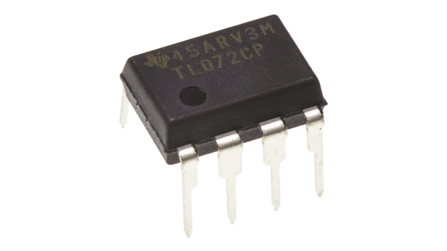
Also, I think your TL072's are Fake, Texas Instruments TL072 do not have the Indent in them at the top centre
If you look at my Picture directly above you will see what a Genuine Texas Instruments TL072 with Machined Socket should look like!!!
I have added the 1N4148 Diodes to the Pic also:

F0304239-01
FAKE
s-l400.jpg
THAT IS NOT NECESSARILY TRUE. DIP-8 TL072s are made in several different plants and do NOT always use the exact same packaging. I have several TL072s that have dimples only, notes only and even some with dimples AND notches. They're all good.

I always carefully examine the legs of ANY IC I get from anywhere to see if they are clean and free of ANY solder. If there is any indication of solder on the legs - and they do not appear like fresh, clean, unadulterated metal legs, there's a very chance they are genuine.
 
Mind you, the Chela circuit has clipping diodes that are ALWAYS in circuit, which means the signal will ALWAYS be getting a 'haircut' by those clipping diodes. Also, it is NOT an exact replica of the EQD Talons after which it is designed. And in either case, it is considered a hi-gain overdrive circuit. Most hi-gain OD builds will add distortion to the signal.

So with that in mind, and you still want to replace the unsocketed opamp - There are at least two ways to remove an un-socketed IC. One is destructive - using fine-tipped clippers, cut each leg of the IC very close to the IC body. That way, each leg can be heated and pulled from the hole once the solder flows. Some clean-up afterwards is often required. Putting it back without a socket is then easy. If you want to put in a socket, it would be best to remove the pot covering the solder-side of that IC location.

The other method is to first remove the pot that covers the solder-side of the IC location, then proceed to desolder each leg of the of th IC until it comes free. More often than not, unless one is very confident with their soldering skills, it is till a good idea to cut the legs from the body of the IC be removing (desoldering) those legs. And with the pot removed, adding a socket will be much easier.

Even for those of us with a high level of soldering/desoldering confidence, removing ICs (or sockets) is always a PITA. Have a good solder-sucker, flux and often-times adding a touch more solder to a joint for removal of a lead/leg can help. A good pre-fluxed solder-wick can also help with the clean up. And remember the 10-second rule. Never have a hot soldering iron on any given solder point for more than 10 seconds at a time - with adequate cooling time between trying to cleanup the same solder joint.

Also, its good to keep in mind that electronics is a fickle mistress and if replacing the opamp does not correct the problem, do not be afraid to use (or make and use) a signal tracer to pinpoint from where the the distortion comes. If you're not familiar with a signal tracer, it's an easy look up and build one with a quick Google search. Mine is just an alligator clip attached to a short bit of insulated wire attached to a 0.1µF 250v orange-drop capacitor which in turn is connected to a six inch piece of insulated wire with about a quarter inch stripped and tinned for touching the various points in the signal path. The cap is simply to prevent any DC from being passed thru the signal tracer should the tip come in contact with a DC source.

In summary, considering the circuit is a hi-gain OD, and these are your first builds, you may want to ponder the idea that it just might not be the circuit for you - and it may actually be performing precisely as intended by the vendor. There are many factors in YouTube video demos that come into play that few consider when making a decision based on such YouTube demos. The amp(s) used, the pickups on the guitar, any off-board/off-screen pre-processing that may have been employed.

When I started building I was disappointed by many builds that I though would be one thing, but turned out differently than I'd hoped. It happens more often than not in the beginnings of the sojourn down the pedal building path.

Good luck!
Thank you so much for the amazing reply full of wisdom!

It could be the circuit but I have a few different LED clipping drives and none of them have the same decay clip issue. But you’re right it may not be the circuit for me. I will try the new TL072s in my socketed pedal first and if that changes it then I will take on the non-socketed chip with your very detailed methods, seriously thank you. I will then try and signal trace it. Then I may try another change or two from suggested users, if that fails it’ll be benched. I may have to buy the real Talons to see if I was close though haha

But hopefully it’s just the chip 👏
 
Resistors are all Good!!!
Do you have a OPA2134 you can try in place for the TL072?
If you don't, you can also try JRC4558.
Update: I didn't realize your Build doesn't have the Socket that was in your initial Test Bench Picture.
the OPA2134 is the smoothest OpAmp I know for pedals!
I use DIP8 Machined Sockets.
I think it maybe the LED Clipping that you may not like,
You may want to try 1N4148 Diodes in that position pictured Below:

View attachment 23519
That is amazing, I actually have both kinds of sockets coming in the mail with the chips so I will switch to the other type, as it seems more popular. And if the chip doesn’t fix what I want, I’ll try the 1N4148 cause why not!

Thank you for the suggestion and cool little photoshop, a picture’s worth a thousand words!
 
In which case, you must feed the beast by building more pedals. If you haven’t boxed it, I wouldn’t. I have quite the pile of builds I decided not to box, some are some I had fabricated myself.
Even though it didn’t go as planned it’s been a blast, already have 3 more builds on the way. If they all go south I may need to reassess but right now I’m just super excited to keep trying
 
THAT IS NOT NECESSARILY TRUE. DIP-8 TL072s are made in several different plants and do NOT always use the exact same packaging. I have several TL072s that have dimples only, notes only and even some with dimples AND notches. They're all good.

I always carefully examine the legs of ANY IC I get from anywhere to see if they are clean and free of ANY solder. If there is any indication of solder on the legs - and they do not appear like fresh, clean, unadulterated metal legs, there's a very chance they are genuine.
There are other manufacturers of the TL072 with the Top Indent, my experience is with Texas Instruments TL072's & Genuine only have the dot.
 
That is amazing, I actually have both kinds of sockets coming in the mail with the chips so I will switch to the other type, as it seems more popular. And if the chip doesn’t fix what I want, I’ll try the 1N4148 cause why not!

Thank you for the suggestion and cool little photoshop, a picture’s worth a thousand words!
As Cybercow suggested, cut the Legs on the OpAmp & remove one at a time with some tweezers & soldering Iron if that is the Issue.
After it is removed, I use a stainless steel Dressmakers Pin & heat the Pad with Iron & very quickly poke the Pin through & wiggle Up and Down at the same time. If the Pin should Stick, just put the Iron on the pin til it releases & wiggle again til it Cools!
It should leave a nice little hole for the socket to go in!
Repeat process til all pads are done.
The Pro's use a good Solder Sucker if you want to invest in one of those!!!
 
Even though it didn’t go as planned it’s been a blast, already have 3 more builds on the way. If they all go south I may need to reassess but right now I’m just super excited to keep trying
Sure, this is a great hobby and it can have somewhat of a learning curve if something doesn’t go as planned. I’ve been doing this for about 10 years and am just now getting around to having OCBs fabricated. This process has been huge in helping me understanding what all those parts do and how to trouble shoot builds.
 
I have some appropriately-sized tiny drill bits for ream-cleaning holes after desoldering — only use them when necessary ie when the solder sucker and/or wick didn’t get all the solder out jamming up the hole-pad.

I drill it out by hand, rolling the bit between my fingers, which is tedious but has better control than a Dremel etc and such fine bits (2mm or whatever) are fragile and snap easily, so you have to be gentle and it takes some time. Did I mention it can be tedious?

At least when done, the pad is clean and free from obstructive leftover solder and the component can be easily installed and soldered.
 
It was
I would wager that the TL072s are the culprit. I recently built 5 Klon circuits and ALL of them had fizzy tails. I replaced the TL072s with ones from Mouser and the problem went away. The batch I first used in the Klon circuits were from Tayda. Good luck!
It was the chips! Sounds beautiful now and far better and more responsive overall. I’ll be sure to post a picture of my painted pedals here tomorrow
 
I have some appropriately-sized tiny drill bits for ream-cleaning holes after desoldering — only use them when necessary ie when the solder sucker and/or wick didn’t get all the solder out jamming up the hole-pad.

I drill it out by hand, rolling the bit between my fingers, which is tedious but has better control than a Dremel etc and such fine bits (2mm or whatever) are fragile and snap easily, so you have to be gentle and it takes some time. Did I mention it can be tedious?

At least when done, the pad is clean and free from obstructive leftover solder and the component can be easily installed and soldered.
Luckily my wife was willing to help and it took about 2 minutes to completely remove, she ran the solder sucker on the back and I’d heat the solder. By myself, it would’ve been a nightmare though
 
Luckily my wife was willing to help and it took about 2 minutes to completely remove, she ran the solder sucker on the back and I’d heat the solder. By myself, it would’ve been a nightmare though
Wow! You have a great wife!

FWIW I rarely like LED clipping. I built a Chela with 2 pairs of 1N4148s instead and like it a lot better.
 
Well yeah, it does... But 2 pairs of 1N4148s probably sounds the same and is faster to type than a pair of 1N4148s with a pair of 1N4001s and then I'd probably need to draw a diagram to explain it. I remember seeing that combo in a Rockett pedal, trying it in something and thinking I liked it so I keep doing it.

Now look at all this typing...
 
Wow! You have a great wife!

FWIW I rarely like LED clipping. I built a Chela with 2 pairs of 1N4148s instead and like it a lot better.
I have 2 extra 1N4001s and 2 extra 1N34As, i will probably try and socket the clipping diodes here soon so I can decide what’s best
 
Last edited:
Back
Top