
Last edited:
“I think I’ve built/ have queued more than enough drive pedals to last me. No more” -me
Nice! Took me a few to figure out the name “chili dog” fwiw lolAdded a Chili Flavour to it!
See Original Post!
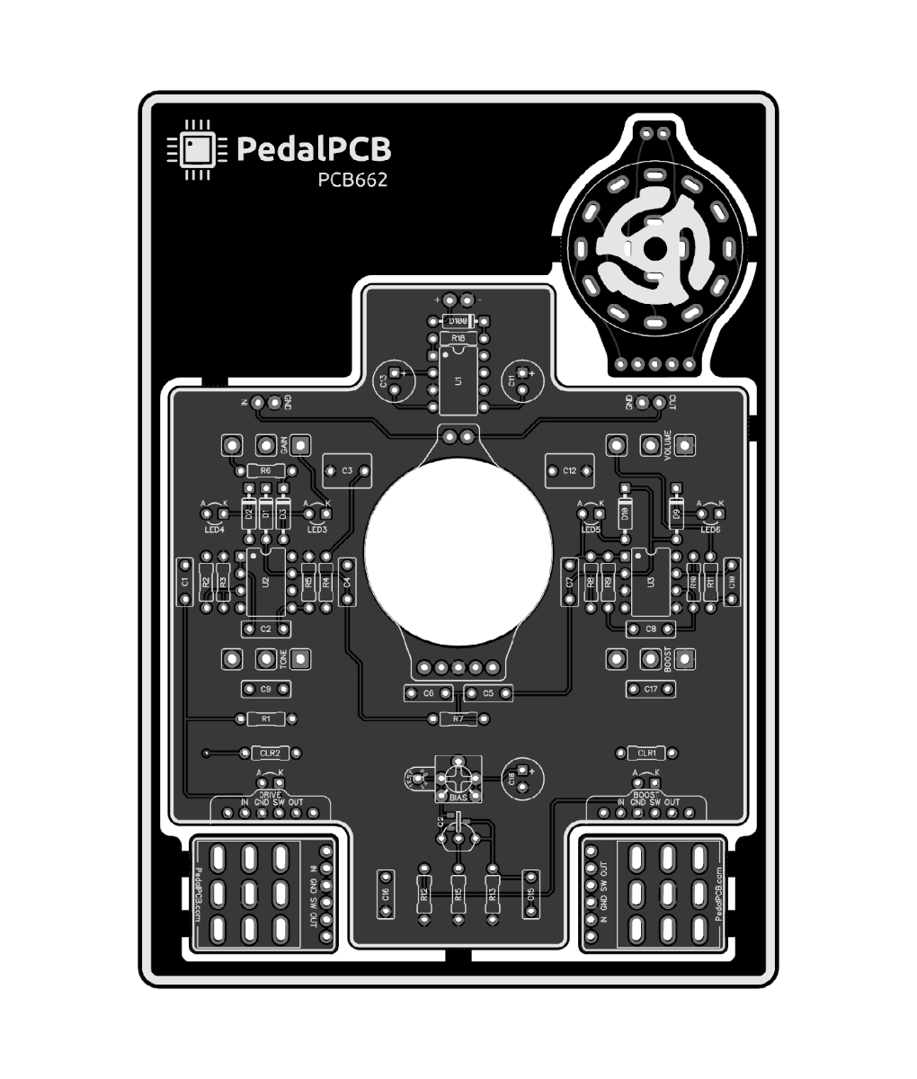
It's definately a 1590BB Build, The 2.5mm pitch in the Op Amp Pins & 5mm pitch on the Pot Leg spacing is a dead giveway it's correct!Nice! Took me a few to figure out the name “chili dog” fwiw lol
Dumb question- your pics look like a 1590bb or bb2, and the project page says 125b. Misprint on the page, or your Proto larger than life? Yes I’m that obsessed in that I went to the project page like 20 times now!
Ahh so the page has an error. No big deal really curious.It's definately a 1590BB Build, The 2.5mm pitch in the Op Amp Pins & 5mm pitch on the Pot Leg spacing is a dead giveway it's correct!
What is the Chili Dog connection Robert???
I’m assuming a BB2 would also work since it’s the same size but deeper.It says 1590BB now!")
I have the board here so made a parts list from that and have everything I think I need except the switch (StompBoxParts I think has one), and the charge pump. Just need to know what to drill.. of course will likely pick up a 1590bb2 instead of the bb I have here just because I like the slightly more legroom to work with)Still need to get my hands on the rotary switch and an enclosure. Planned on getting this one done before the pcb was officially released but my spring break wound up dominated by my projects from this semester.
Gonna be attempting a linocut graphic for this one though so I can avoid the wait time for a UV print— found some speedy-cut knockoff stuff that’s softer than typical battleship grey (which will assist in printing on a solid surface), but much stiffer than the typical speedy-cut which I find is too soft to retain fine detail and is prone to distortion and squish when printing it as a ‘stamp’
I’ve been going with the assumption that the drill template would be equivalent to the Acetylene Overdrive minus the cut and treble pot holes, with the toggle switch hole enlarged of course to accommodate the rotary switch.I have the board here so made a parts list from that and have everything I think I need except the switch (StompBoxParts I think has one), and the charge pump. Just need to know what to drill.. of course will likely pick up a 1590bb2 instead of the bb I have here just because I like the slightly more legroom to work with)
I make my layouts using the PCB layout for the drill template, its easy if it has the rotary & toggles as they are where the PCB locates in the enclosure.I’ve been going with the assumption that the drill template would be equivalent to the Acetylene Overdrive minus the cut and treble pot holes, with the toggle switch hole enlarged of course to accommodate the rotary switch.
@Robert can you confirm?
I believe this is the parts list. Can’t guarantee the accuracy as my eyes are old lolI think I used the Acetylene as a starting point but there might be some deviation. I'll post the drill template for you shortly.
| 1 | 100R | 1 | 220p |
| 2 | 1k | 1 | 500p |
| 1 | 2.2k | 2 | 1.5n |
| 1 | 3.9k | 1 | 10n |
| 2 | 4.7k | 3 | 56n |
| 1 | 10k | 1 | 68n |
| 2 | 22k | 4 | 100n |
| 1 | 47k | 1 | 220n |
| 2 | 100k | 2 | 22u |
| 4 | 1M | 1 | 100u |
| 1 | TRIM 50k | 1 | 1N5817 |
| 2 | A100k | 3 | 1N4001 |
| 1 | B10k | 2 | 1N60P |
| 1 | B100k | 4 | 3mm Red LED |
| 1 | 4P3T Rotary | 1 | J201 |
| 1 | ICL7660SCBAZ | ||
| 2 | TL072 |
You realize that this is the PedalPCB version built by Robert back in February in a standard 1590BB ???Nice! Took me a few to figure out the name “chili dog” fwiw lol
Dumb question- your pics look like a 1590bb or bb2, and the project page says 125b. Misprint on the page, or your Proto larger than life? Yes I’m that obsessed in that I went to the project page like 20 times now!
Yes, but didn’t notice him saying it was a standard BB and not a BB2, which I believe is the same but just a touch taller (3mm I believe). Old age eyes can’t tell the 2 apart at sight.You realize that this is the PedalPCB version built by Robert back in February in a standard 1590BB ???
https://forum.pedalpcb.com/threads/lerxt-by-tor.20967/#post-264666
Bb is fine. Wasn’t sure of the clearance with the rotary breakout. Good news though as I had a spare 1590BB here already so that saves me a bit. Just too bad it’s blue and not Barchetta red! lolYep, it's a standard 1590BB.
The 125B thing was just an error. New product pages are created by duplicating existing pages then filling in the info, every once in a while I miss one of the fields.