Chop Shop Troubleshooting

jrhevron

Active member
HI all... I build a pedal or two a year, so I'm by no means an expert, but not a total noob.

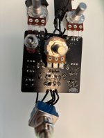
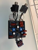
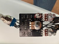
I just put together a Chop Shop/Barbershop drive. I populated the board with components from smallbear and reused a power jack and in/out jacks from an old build. Got it all set... and no signal... signal on passthrough/when footswitch off. Pots do nothing and trimmers show no voltage and don't change anything.

I went through and probed and audio signal seems to be going all the way through, just no effect. I am having a voltage issue. I get 9V at R100 but no voltage at the trimmers/pads or at R11 or Q3.

I've reflowed and took the switch out just to make sure that that isn't an issue.

Any ideas on what to do? Clearly seems like a voltage issue... something is killing it after R100, I guess?
 
Last edited:
I think that part of my question is how I would go about following the voltage path based on the schematic. Clearly, it seems like the voltage is dropping somewhere or being shunt or not grounded. I know how to follow the audio signal, but it's less clear on the voltage path.

Actually... took another look at the schematic and it's clearer to me now.
 
@Robert I did more testing and was able to trace the 9v through to the end. Not sure what the issue was before.

Still, the pedal isn’t working.

I did an audio probe and found that the signal dies at C4. It makes it to the jfet—one side—and then doesn’t show up at either of the other poles. I do get continuity from C4 to one of the other jfet legs.

I feel like the issue has to be in this area, but I’m all out of ideas. I replaced the jfet and reflowed everything.

Any other ideas? :)
 
Last edited:
Not pretty! But I've reflowed and checked between solders for bridges. Also, I left the legs on the transistor for now.
 

Attachments

  • IMG_3448.jpg
    IMG_3448.jpg
    238.2 KB · Views: 17
  • IMG_3449.jpg
    IMG_3449.jpg
    265.8 KB · Views: 17
Does the voltage measured at the two test points change when you turn their trim pot?

What voltages do you measure on each pin of the two JFETs?

View attachment 97815
Just measured: one probe on the plus of the socket coming in and the other probe to each of the ends of the J201.

JFT 1:
G: 8.5
S: 9.2
W: 9.1

JFT 2:
G: 8.6
S: 9.1
W: 9.1

voltage doesn't change when you adjust the trim... maybe the issue is in the trim pots?
 
Last edited:
I took the switch off, took the pcb off, and reworked it just to make sure there wasn't a short on the switch. All works fine. When you click it, it bypasses and the signal flows through fine. When engaged, no sound and pots don't affect that.
 
If i remember correctly, I don't think you're supposed to have any voltage at the gate or the JFETS. The backside of your board needs some cleanup. Use some isopropyl alcohol and a toothbrush to clean off all the flux. Be careful no to get any inside your pots. Then post updated pictures. It was pretty blurry before.
 
If i remember correctly, I don't think you're supposed to have any voltage at the gate or the JFETS. The backside of your board needs some cleanup. Use some isopropyl alcohol and a toothbrush to clean off all the flux. Be careful no to get any inside your pots. Then post updated pictures. It was pretty blurry before.

I'll clean it up... def needs that.

Can excessive flux cause shorts? I should probably know this :)
 
Do you have other JFets to try out there? Try reflowing all other solder joints.
I have reflowed a few times... also had a pack of 5 smd jfts from pedalpcb. I went in and replaced the first one. Is it possible to have bad SMD JFTs? I mean, I know that anything is possible.

Also, thank you!
 
Last edited:
Back
Top