Chrystal Drive and Shika Fuzz, no voltage at any transistor

Pauleo1214

Well-known member
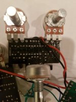
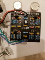
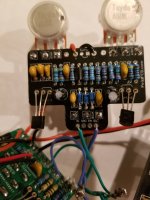
I am wondering if I used an incorrect resistor somewhere. I am building a combo build that combines the Crystal Drive and Shika Fuzz in parallel with a clean signal blend.

While the clean blend works, I get no sound from either board. I measured 9 volts going to each positive terminal of each board as well as at the diode. There is no voltage whatsoever at the transistors at each board. Can anybody spot anything wrong?
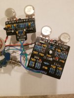
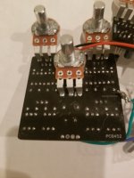
20220219_212040.jpg

20220219_212109.jpg
 

Attachments

  • 20220219_212126.jpg
    20220219_212126.jpg
    183 KB · Views: 6
Can confirm 9 volts either side if the 5817 for both.
Oh yeah, you said that in the initial post, my bad. You should be able to follow the trace to see where the power rail goes after that. On the Shika, do you have 9V on one side of R5, 11, 16, 20. or 22? Those are the biasing resistors through which the power goes to the transistors. The pictures are sort of small, dimly lit and not too clear when I enlarge them.
 
Test your Voltages on the Red Circle with DMM, Black probe on Green Circle:
View attachment 23252View attachment 23253
There is no voltage going to the transistors on either board.
Oh yeah, you said that in the initial post, my bad. You should be able to follow the trace to see where the power rail goes after that. On the Shika, do you have 9V on one side of R5, 11, 16, 20. or 22? Those are the biasing resistors through which the power goes to the transistors. The pictures are sort of small, dimly lit and not too clear when I enlarge them.
I will report what i get soon. I will also try to take better photos, the file size limits for uploading jpegs are troublesome.
 
Oh yeah, you said that in the initial post, my bad. You should be able to follow the trace to see where the power rail goes after that. On the Shika, do you have 9V on one side of R5, 11, 16, 20. or 22? Those are the biasing resistors through which the power goes to the transistors. The pictures are sort of small, dimly lit and not too clear when I enlarge them.
Following back up to confirm that there is no voltage at either of the biasing resistors...I get 0.24V, 0.24V, 0.3V, 0.3V at Qs1-4 respectively.

I get 0.27V and 0.3V at either MPSA18 on the Chrystal drive. This one really has me stumped!
 
I agree with jimilee, I would get the individual Circuits working first before applying the Clean Blend circuit!!!
Thank you for the advice, I appreciate it. Removing both of the circuits from the Clean blend and testing them individually resulted in the same issues.

I should have been more clear in my first post mentioning that the circuits do in fact work and work as they are supposed to but only when I press on the back of certain places with my finger. I haven't deduced exactly where on the Chrystal Drive but on the Shika Fuzz, it works normally when pressing on the back of C12 and the three resistors below it. This makes me think the board itself might have a severed trace.
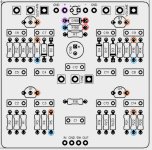
NOTE: I have used this Layout as the Black PCB Board Layout is an Older Picture & does not match what is written below!
Can you confirm your board matches the one Pictured below???
If it is R21-47K looks like 4K7 on your build???


Can you do a Continuity Test on the Matching Circles :

Shika Continuity Test.jpg
 
Last edited:
NOTE: I have used this Layout as the Black PCB Board Layout is an Older Picture & does not match what is written below!
Can you confirm your board matches the one Pictured below???
If it is R21-47K looks like 4K7 on your build???


Can you do a Continuity Test on the Matching Circles :

View attachment 23300
My eyes are going bad!

R21 was a 4K7. I did not have any 47Ks on hand so I subbed in a 51K and it worked. Consequently, that was the same problem for R7 on the Crystal Drive. Both are in working order. Thank you both for your help!
 
Back
Top