Chuck D.Bones Mojito Mk3 switching issue

Kris100

Member
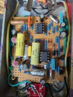
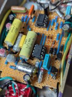
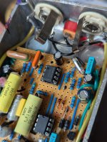
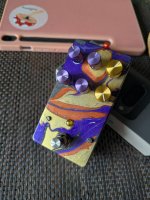
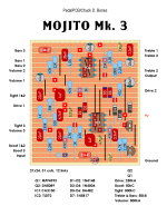
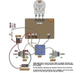
Hi All, I just build this Mojito Mk3 overdrive based on the attached vero layout from dirtboxlayouts and while it generally works when engaged, the bypass switching is not working well - ie when I hit the footswitch, there is always a bit of delay before the pedal turns on (signal seems to quickly fade in), same happens when I turn it off. I wired it in true bypass following Madbean's wiring scheme which I am also adding as attachment for reference. The layout has not been verified before and the thread on Mojito MK3 in this forum no longer includes the schematic so I can't really troubleshoot apart from checkiing my build against the layout which seems to be good. I checked the following:

- strip cuts and I double checked there's no continuity across any of them
- placement of links and continuiuty across them
- all component placement including polarity of diodes and caps
- I double checked there's no unintended shorts between strips
- all components were tested before being soldered in (I'm using some salvaged caps from old tape players etc but always test before using)

Perhaps there's someone here who built this on vero and can relate and share some ideas for troubleshooting or see something obvious on the layout I used which is not correct
 

Attachments
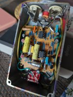
  • 1000024921.jpg
    1000024921.jpg
    427.6 KB · Views: 15
  • 1000024922.jpg
    1000024922.jpg
    451.3 KB · Views: 14
  • 1000024923.jpg
    1000024923.jpg
    414.1 KB · Views: 13
  • 1000024924.jpg
    1000024924.jpg
    402.8 KB · Views: 12
  • 1000024925.jpg
    1000024925.jpg
    483.7 KB · Views: 14
  • PedalPCB Mojito 3_Honeybee+.png
    PedalPCB Mojito 3_Honeybee+.png
    200.8 KB · Views: 19
  • tb wiring.JPG
    tb wiring.JPG
    83.3 KB · Views: 18
Last edited:
Doublecheck your footswitch wiring. When there's a bypass related problem it's the footswitch 99.99% of the time. (Because at that point the signal isn't even going thru the effect)

My guess is that it's wired in a way that ground is only connected to your board when the footswitch is activated. When it isn't activated, it has no power - so once you hit the footswitch it effectively has to 'boot up' - from what I can read from this circuit that means charging the 100uF input filtering capacitor through the 47R filtering resistor (just a few milliseconds) and then charging the 10uF VREF capacitor thru the voltage divider made by the two 47K resistors (much slower - just over 2 seconds) So make sure that ground is always connected to the effect and the only thing that the footswitch is switching is the bypass and the LED.

(Also check for possible shorts when it's bypassed)
 
Thank you for the suggestion. I went around the board and measured voltages which seem fine - both when board is bypassed and when it's engaged there's constant ca9v present. There's also no brief dip in voltage across ICs when I hit the footswitch. All ground connections are solid and board is grounded at all times. I suspected the footswitch at first but when I check for continuity it looks to be working fine - solid switching across all poles with no shorts etc.
 
I'm no electronics engineer, and have no experience with vero per se, but it might be useful to offer a look at the solder side as well to see what's up with the connections and cuts. Particularly as it strikes me that it would be easy to make a transposition/mirroring error in vero.

You can also just try rewiring the 3PDT and see if that makes a difference. Robert's way is straightforward and logical for me, and out of habit, probably, I stick with that.

Having said that, usually 3PDT issues are usually binary: it works/it don't work. But, I have had weird ass crackles and volume jumps due to poor soldering, so there's that. In this case, I concur that it sounds like it might be related to something with a capacitor charging, and @z2amiller 's idea makes sense to me, but if you have 9v after d7 with the switch off, then that rules it out.

The thing that solves my problems 9/10 times is to grab a schematic, and go through the troubleshooting order of operations:

1. Visual check of components and connections

2. Check every single component value against the schematic, and check for correct orientation of polar/pinout components (capacitors, diodes, ICs, and transistors). Since it looks like you have a lot of vintage caps, I always check the readings on those before installing in the circuit. Could be a bad cap, maybe?

3. Device-assisted checks:
1) voltage readings to the ICs and transistors (DMM)
2) continuity checks between components, off board elements, and ground (DMM)
3) audio probe (homebrew)

4. Reflow
 
Last edited:
I'm no electronics engineer, and have no experience with vero per se, but it might be useful to offer a look at the solder side as well to see what's up with the connections and cuts.

You can also just try rewiring the 3PDT and see if that makes a difference. Robert's way is straightforward and logical for me, and out of habit, probably, I stick with that.

Having said that, usually 3PDT issues are usually binary: it works/it don't work. But, I have had weird ass crackles and volume jumps due to poor soldering, so there's that. In this case, I concur that it sounds like it might be related to something with a capacitor.

The thing that solves my problems 9/10 times is to grab a schematic, and go through the troubleshooting order of operations:

1. Visual check of components and connections

2. Check every single component value against the schematic, and check for correct orientation of polar/pinout components (capacitors, diodes, ICs, and transistors). Since it looks like you have some vintage caps, I always check the readings on those before installing in the circuit.

3. Device-assisted checks:
1) voltage readings to the ICs and transistors (DMM)
2) continuity checks between components, off board elements, and ground (DMM)
3) audio probe (homebrew)

4. Reflow
You're right, I ahould have made some picks of the underside of the board when it was all apart, will look into that.

I checked all components (both placement and values, including measuring all caps before soldering in as they obviously could be an issue). Problem with checking this build is that schematic is not available, just the vero layout where the person who made it included a link to ppcb forum thread where schematic was meant to be available. Vero layout was not verified to be correct but I assumed that even if its wrong I can fix it with the schematic... Never knowing it was taken down from the forum thread :)

I'll keep checking but appreciate all your advice.
 
Back
Top