Crunch Captain Deluxe low volume?

ragamuffin

Active member
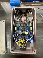
I recently built a Crunch Captain Deluxe and it sounds good and seems to be working but overall volume is low.

With the Mode switch in the middle (classic Crunch Box/high gain) and clipping switch to the right (LED clipping, the lighter clipping option) with Gain at noon I have to nearly max the volume to get unity level. In the heavier clipping setting (to the left) I can hardly reach unity.

Does this sound normal, or is something off?

IMG_2507.jpg
 
Last edited:
Lest do a quick bias check, then inspection.
With power on and no signal, verify these voltages (±0.5V).
IC1-1: 0V
IC1-4: -8.4V
IC1-7: 0V
IC1-8: +9V
IC2-1: +4.5V
IC1-4: -8.4V
IC1-7: +4.5V
IC1-8: +17V
Don't bother measuring the other pins because the measurements may not be accurate due to the meter loading the circuit.

Remove the board and do a thorough visual inspection of both sides using light and magnification. My wager is that there is either an incorrect component value (I didn't spot any), a solder splash, a missing or cold solder joint. I built one of these and it goes plenty loud, depending on the setting of the CLIP switch. Check all of the pots too. C19 is melted on top, it may or may not be damaged. The soldering looks pretty good, but I can't see every joint. Look for solder debris hiding under the ICs.

One more thing: disk ceramic caps are noisy and unreliable. They should not be used in a pedal circuit. Depending on availability, use silver mica, film or MLCC. Let's get this pedal working first, then think about replacing those caps.

Ok with the pedal plugged in, no signal, I've got:

IC1-1: 72mV
IC1-4: -6.5V
IC1-7: -168mV
IC1-8: 7.2V

IC2-1: 3.65V

IC3-1: 7.2V
IC3-4: -2.7V
IC3-7: 3.9V
IC3-8: 7.2V

:unsure:
 
Your charge pump isn't pumping charge to the +18V rail. Your ±9V is low. Are you powering this with a battery?

I suspect that there is something wrong with C104. Cold or missing solder, broken pad/trace or broken part.
 
Last edited:
Ok, I remember one mod I did to this thing. There is too much voltage drop in R100, IMHO. I reduced it to 15Ω in mine. I went back & updated the voltages in post #20. All of your voltages look good except IC2-8. Check that one again please.
 
OK, so your DC voltages are all good, or as good as they can be given the power lost in R100. The problem is elsewhere, so time for a detailed inspection. If you haven't already, you might want to read my build report (link in post #25). It will give you an idea of what performance to expect.
 
Last edited:
Forgive me for butting in out of left field. Did you give each joint on the footswitch sufficient time to cool off before the next?

It looks a bit odd to me but could be the light. It’s quite possible to melt the inner goo if one overheats the switch.

And by all means ask me how I know 🙃
I'll definitely check it out! I had a damaged switch (probably overheated) on one of my other recent builds
 
Last edited:
You can bypass the footswitch temporarily by soldering the in/out audio wires to the in/out on the circuit board. Leave the SW and GND wires disconnected, as all they do is turn on the LED when the board is on
 
Would that be the left or right pin with the flat side of the transistor facing forward? I'm getting -0.62V on the left pin and 13.8V on the right pin
For all TO-92 devices, with the flat side facing you and pins pointed down, the pins are numbered 1,2,3 going left to right. Which pin is emitter, source, etc. depends on the part number. Best to consult the datasheet when in doubt. Or plug it into a transistor tester and it will ID the pins.

The emitter voltage is good BTW.
 
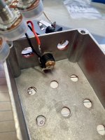
While I was fooling around with everything one of the DC lugs snapped off. So I guess further explorations will have to wait until I get a new one in the mail! I'm getting an outie this time so it will have room. The lug was already weak because I had to bend it to make it fit, so I had ordered a new DC jack the other day already.

IMG_2541.jpg
 
Back
Top