digitalyeti
Member
Hey All,
Long time lurker, first time poster. Have been having a blast building pedals during lockdown. It has been a fantastic way to distract myself from what I should be doing, mainly writing my PhD dissertation. In all honesty, I think I enjoy building the pedals more than even playing the guitar.
So the reason for this post. I am building my fifth pedal — haven’t had any issues with my previous builds that some basic troubleshooting could not fix. However, the Deflector is giving me some problems.
Everything assembled easily. I have sound when turned off and sound when turned on. However, when turned on, my signal is the same as when off — in other words the signal is not being changed by the pedal.
I did the usual troubleshooting — switched out all the ICs (thank goodness I socketed them) and double checked all the solder joints and reflowed them to double check everything. Triple checked all my component values and made sure they were the right polarity (stripes down) Still, no go.
Using an audio probe, I am receiving signal at pin 2 of the FV-1, which matches what I should be getting based on the schematic. (Most of the other FV-1 builds from PedalPCB look for signal on pin 1, but according to the schematic I believe that the Deflector is different). I do not have an output signal from pin 28. I do get a faint clicking sound, which is not present in the final output of the pedal at the output jack.
I have continuity between pin 14 of the FV-1 and pin 6 of the EEPROM, as well as pin 15 of the FV-1 and pin 5 of the EEPROM. I have the proper 3.3v going to pin 13 of the FV-1.
When I short the voltage going to pin 13 (by shorting R4) so as to use the internal FV-1 programs, I DO receive a signal at pin 28 of the FV1, but it is not modulated or changed.
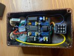
This leads me to believe that I might have a bad EEPROM. Could I be missing anything else? I have attached a picture of the front of the board. I would rather not pull it out again and bend the Pots to show the back, but will if you all think it can help.
I have a CH341A USB flasher and can trying flashing an EEPROM if someone can send me the hex or bin file that is correct for the Deflector. Otherwise, I might ask about getting a new EEPROM, unless I am missing something . . .
You all rock, look forward to hearing your thoughts!


