Elktronics
Active member
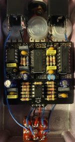
Hello,
Just finished up a Deflector Reverb, and I’m getting no sound. Bypass works fine, but nothing when active.
The L78L33 gets warm/hot to the touch, but I’m not sure if that’s ok or not.
Everything is socketed, including the regulator. I’m powering this with a one spot.
Does anyone know what voltages I should be expecting and where I should begin audio probing?
Thank you