Design Challenge #1

Chuck D. Bones

Circuit Wizard
We've read posts here where someone says "I've got this part and I want to figure out what to do with it. How would I design this into a pedal?" Usually the design process works the other way, but there's no reason not have a bit of fun and try to design something around specific parts. It's the accidents and out-of-the-box thinking that spawn new and creative designs.

So here's the challenge. Design a pedal using this part:

https://www.goldmine-elec-products.com/prodinfo.asp?number=G25209

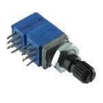
It's a B20K 4-gang pot. The only rules are that every gang must be used and they must all do something useful. 4-gang B20K pot - EG G25209.jpg
 
We've read posts here where someone says "I've got this part and I want to figure out what to do with it. How would I design this into a pedal?" Usually the design process works the other way, but there's no reason not have a bit of fun and try to design something around specific parts. It's the accidents and out-of-the-box thinking that spawn new and creative designs.

So here's the challenge. Design a pedal using this part:

https://www.goldmine-elec-products.com/prodinfo.asp?number=G25209

It's a B20K 4-gang pot. The only rules are that every gang must be used and they must all do something useful. View attachment 7458
I’ll have to come back to this after I read through some of the theory articles you promised to post. Looking forward to it.
 
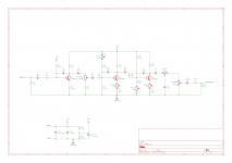
This might actually work. Might have to breadboard it after figuring out actual values for resistors and caps. As is, all resistors and caps are arbitrary, starting points if you will. Nothing was calculated so... But the premises is as you increase the gain on Q2 and Q3 you also change the base bias voltage causing Q2 to shift up and hard clip the top of the signal and Q3 to shift down and hard clip the bottom of the signal. It may be kinda harsh though. Also I do not have a 4 gang pot symbol so I used a dual gang pot twice and gave it the same name. And R3 may need to be tied to +9Vdc, I was just having fun with VAA. TDC.png
 
I tried ganging together the tone controls in a TMB stack, but could not find an interesting combination.

Here's an idea: stack four clipping stages, each with a gain control and gang all four gain controls together. Make each stage different, some hard clipping, some soft clipping, some symmetric, some asymmetric, different bass & treble rolloff in each stage, etc. As the gain is turned up, more and more of the clippers come into play. Kinda like an M I Audio Tube Zone, but with four stages instead of two.
This could work in a Big Muff circuit then.
 
Be aware, the 4 gang potentiometer body measures just over 17mm in height, A standard 16mm with dust cover is around 10mm.
16mm PCB Long leg pots will have to be implemented if a PCB style board is used.
 
Be aware, the 4 gang potentiometer body measures just over 17mm in height, A standard 16mm with dust cover is around 10mm.
16mm PCB Long leg pots will have to be implemented if a PCB style board is used.
Naw Man! Just horizontal mount this bad boy, have it sticking out the left side of the enclosure and put a 4 foot stick shift on it, Wah pedal to the right of the enclosure, and give a whole new meaning to the "drive" part of overdrive! :ROFLMAO: :ROFLMAO: :ROFLMAO:
 
Might be interesting to design the pots so a rotation will increase gain on one or two points while decreasing gain on the others. Then it could be a see-saw adjustment rather than raising or lowering all of the gains at the same time.
 
Naw Man! Just horizontal mount this bad boy, have it sticking out the left side of the enclosure and put a 4 foot stick shift on it, Wah pedal to the right of the enclosure, and give a whole new meaning to the "drive" part of overdrive! :ROFLMAO: :ROFLMAO: :ROFLMAO:
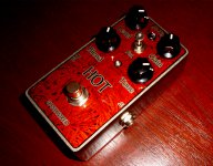
Here's a stick shift on my Hot Wired Distortion with Blend knob Mod from 2017!
I built 3 - Dual, Drive & Distortion versions :

Hot Wired Distortion with Blend Pedal 1.jpg
Hot Wired Distortion with Blend Pedal 2.jpg
 
Here's a stick shift on my Hot Wired Distortion with Blend knob Mod from 2017!
I built 3 - Dual, Drive & Distortion versions :

View attachment 7478
View attachment 7479
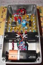
I always have to see the inside of Music6000's pedals.
1. The rivet board construction is beautifully crafted.
2. His photoshop skills make me wonder whether the pedal is real or imagined.

WARNING! Duracell batteries are leakers and will puke electrolyte all over the inside of your precious pedals.
 
Last edited:
Be aware, the 4 gang potentiometer body measures just over 17mm in height, A standard 16mm with dust cover is around 10mm.
16mm PCB Long leg pots will have to be implemented if a PCB style board is used.
It was mainly a thought experiment, but the pot body is short enough to fit inside a 125B box. The board, or at least part of it, could be perpendicular to the front panel.
 
I always have to see the inside of Music6000's pedals.
1. The rivet board construction is beautifully crafted.
2. His photoshop skills make me wonder whether the pedal is real or imagined.

WARNING! Duracell batteries are leakers and will puke electrolyte all of the inside of your precious pedals.
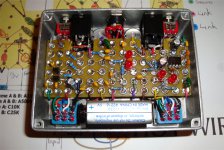
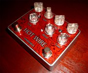
Here you go Chuck, Here's the '' Hot Wire '' Dual Pedal I Built!

HOT WIRE Custom Overdrive Distortion Peda1 2.jpg
HOT WIRE Custom Overdrive Distortion Pedal 1.jpg
 
WARNING! Duracell batteries are leakers and will puke electrolyte all of the inside of your precious pedals.
I only use Batteries for demonstration purposes!!!
None of my pedals have Batteries, It's just an option for those that like to use them.
 
And where do you get the boards from, they RULE!
I purchased a 1 metre x 600mm (3 foot, 3 inches x 2 foot) offcut of 2mm FR-4 around 7 years ago & Design, cut, drill & 2.5mm Eyelet every one to suit the Build.
I have a 2mm thick aluminium drilling template that I use to drill up to 16 / 1.6mm holes for Op Amp sockets.
I twist 24 awg insulated pre tinned wire around a dress makers pin twice & slide it over Socket pin and solder in place to hold socket firmly in place and to edge of appropiate Eyelet.
 
Back
Top