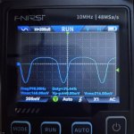
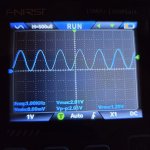
Hey folks, I've been doing some testing with diodes using my breadboard, except I've run into an issue, no matter how I hook up the diodes, I'm always getting asymmetric clipping. It doesn't matter whether they are silicon, germanium etc.
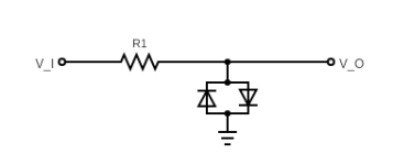
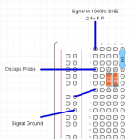
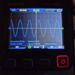
This is as measured with my oscilloscope using a 2.4v peak to peak 1000hz sine. I'm pretty sure my bread board layout is equivalent to a regular hard clipping arrangement like this. R1 is a 1k resistor, though same result without the resistor.
I feel like I must be missing something here? Shown below on the oscope is a pair of 1n4148
