joelorigo
Well-known member
I'm getting back to this project after being distracted by several other things. One question, where exactly do I connect the ground wire to?

I'm getting back to this project after being distracted by several other things. One question, where exactly do I connect the ground wire to?
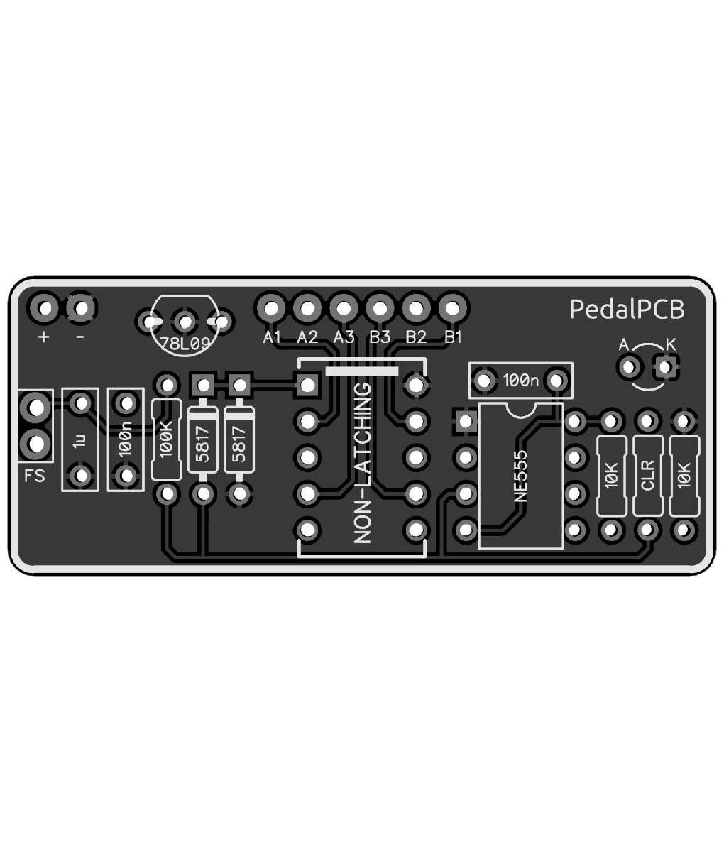
If I understand this correctly, all the sleeves of the jacks are connected together, and then to the lower left lugs on the switch as shown in the diagram. No power, no LED, just passive.All grounds get connected together, the ground from the jacks, switch, and negative power supply if you are using power
Thanks again!
Hmm, what’s this going to accomplish? I don’t know what an intelligent relay bypass is.Well, you could just build 2 mono loops with gorvas and mount them really close together.
Don't see why one couldn't wire up 2 intelligent relay bypass boards in one box. The footswitch is just switching ground.
It's a ppcb bypass board. You would use the in and outs that would go to the pcb as your loop sed and return. Really, you could use any relay board here I believe, as long as they are using the footswitch to switch ground only. Haven't check all the build docs. With the IRB, you get some cool momentary stuff that may be useful, or not. If not, I'd stick to a normal relay bypass.Hmm, what’s this going to accomplish? I don’t know what an intelligent relay bypass is.
Hey sir glad you made it. I also want to create my own. Can you share your schematics please? Thank you good sir!I finally got around to trying to build this. It works! Thanks for all the advice.
Hi! All I have is this attached file. And then as in post #25:Hey sir glad you made it. I also want to create my own. Can you share your schematics please? Thank you good sir!


