Quasimofo170
New member
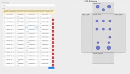
I am creating a template in libre office draw to create pedal art for printing. I am using a drill guide I found for pedal pcb “125b pedalpcb 6-knob type 1” to create the drill holes in my layout. However I am not sure how the drill marks are measured on the layout. When I create the circles for the holes they do not line up at all in libre office. I think it may have to do with how the actual pedal enclosure is measured on the diagram. The diagram only shows drill dimensions and not for the enclosure itself. I used some I found for the 125b enclosure but it’s still not correct. Can someone tell me what size the enclosure is on these diagrams or give me some insight on what I might be doing wrong.
Also I understand how libre office can have different positions for different parts of the circle and I made sure they were all from the center point.
Also I understand how libre office can have different positions for different parts of the circle and I made sure they were all from the center point.