When designing a drill template for a build that will use this breakout board, how do I determine the exact distance between the 3PDT switch and the LED bezel for the drill holes?
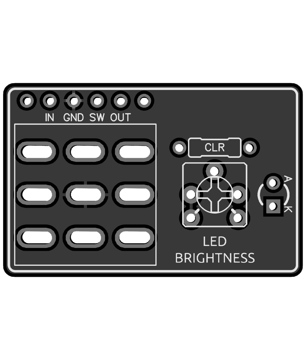

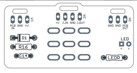
Another rookie question…what are the 2 unlabeled contacts beside the other connections?

Gotta power the LED but I think Aion has pads for that.Thanks for the tips. So far, I’ve only built AION kits and the footswitch board has a lot more going on, including +v. Am I correct in assuming that is for the power supply circuit and the footswitch doesn’t require +v ?
Sorry for the confusion, I’m not mixing ppcb and AION boards, I was just pointing out the differences, specifically that the AION footswitch board contains the power supply circuit. With the PPCB breakout board, where does the LED get power from? Do I jumper from the main board?Gotta power the LED but I think Aion has pads for that.
I would advise against mixing daughter boards between ppcb and Aion if you e just been doing kits. They each have their own way of doing things. It's doable but odds are you'll end up in the troubleshooting section before it's over with.
The two middle solder pins are the LED circuit and groundSorry for the confusion, I’m not mixing ppcb and AION boards, I was just pointing out the differences, specifically that the AION footswitch board contains the power supply circuit. With the PPCB breakout board, where does the LED get power from? Do I jumper from the main board?
20.32*
20.3* ain’t nobody got time for better tolerance!20.32*
When your bit hits the box every fraction of a millimeter counts!Tenths of a millimeter? Man I'm doing good if my bit hits the box.