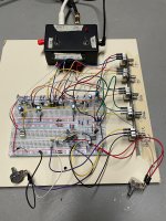
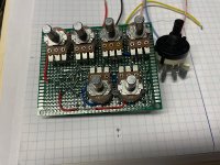
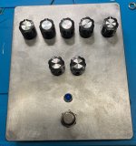
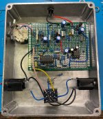
Well, this is my most ambitious breadboard.
For new breadboard bakers: Don’t get discouraged when your board doesn’t work. This is a monster with 7 pots, 3 different voltages, 2 IC’s, and 4 transistors. And it was crippled by a missing jumper and an out of place resistor leg. Just walk away, and come back later with a clear head and trace it out.
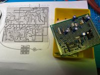
I saw the strip board layout over at dirtboxlayouts and had the idea to translate it onto a breadboard before committing to build it.
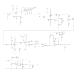
I worked out the schematic from the dirtboxlayout. I picked away at it in the evenings while watching tv. Once I had the schematic figured out, I built the breadboard and of course it didn’t work.
Then it collected dust for 2 months until tonight. I had 1 resistor leg out of place and 1 power wire missing.
So after 4 months, here it is. It’s a big ole beast and it sounds awesome! One of the pots is standing in as the internal trimmer, just because it was easier to place. And the FAC rotary is missing (I just swapped the caps by hand to test them out).
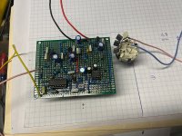
I’m definitely going to build and box it. I’m fiddling with ways to board mount some or all of the pots. Or maybe move the schematic to perfboard, if that provides a nicer layout.
